| ||
Visit MustangSteve's web site to view some of my work and find details for: FYIFORD Contributors' PICTURES - Power Brake Retrofit Kits for 65-66 Stangs - Classic Mustang FAQ's by MustangSteve - How to wire in a Duraspark Ignition - Mustang Ride Height Pictures and Descriptions - Steel Bushings to fit Granada Spindles to Mustang Tie Rods - Visit my EBAY store MustangSteve Performance - How to Install Granada Disc Brakes MustangSteve's Disc Brake Swap Page - FYIFORD Acronyms for guide to all the acronyms used on this page - FYIFORD Important information and upcoming events |
Offline
jon, great thread, wish I had found that sooner. I didn't understand what the implications of having jounce that is not in parallel with the chassis and what your thoughts were on moving the front pivot, or if you have a good thread. Will definitely be looking through corner-carvers a whole lot more.
barnett, not sure where else your trying to defy basic laws of math/physics with your parallel arc/line, but:
1) I said the lca reduces down to a rotation axis (line through pivot points) and a point (lbj) that is rotated about that axis and the rotation center is at the intersection (rear pivot point) of a perpendicular line to the point, I have shown you this is true at least 3 different ways that should give you pause. The movement of the strut rod through 3d space makes the face of a cone, not a Seesaw. It is most definitely not moving the way jkordzi described.
2) Once assembled, the strut rod was like your 10' arm .. in the mud, it took a lot of effort to move it. The bushings are in fact rubber, a brand new Moog K8122 set. If you look at the design, when deflected, it forces equal and opposite compression on both sides so substituting any identical material used on both sides should work the same way. The arm itself was quite fluid and could deflect very easily back and forth, it wasn't influencing the strut-rod. I likely rotated it further up and down than it could have been while connected to a car so that any change would be exaggerated.
3) The CAD packages I have access to don't let me easily link components together and model them, so I wrote my own, it started with a simple caster/camber table and added the 3d rendering so I could verify everything moving in the right direction at the spindle as I deflect the chassis and steering. I know the calculations are correct out to the spindle, but not taking into account things like how a turned wheel affects ride-height, which then affects the caster/camber relative to the road .. yet.
4) I suggest you take your mustang apart, map it, and show us how much of the ~700 lbs of weight on your spring is moving sideways to deflect your strut rod. If there is something significant there I would like to know about it. I don't have a problem agreeing to just disagree while your mopping those floors
This mis-interpretation of an arc is easy to fall into, it was my initial impression too, and didn't pay much attention until I came across the paper thing in the vmf thread with that longer strut rod, and maybe corner-carvers is the better place to discuss this.
Back to the original post, the corner-carvers thread jon linked shows where it took ~28 lbs of force to deflect the strut rod, I can believe that after seeint it first hand, it is really pretty bound up. It would be interesting to hear from someone who returned to stock strut-rods how they felt about the handling before and after, sometimes imrovements are felt more going backwards.
Offline
I thought that would interest you afnid. I don't have another link that speaks to load path vs. non parallel control arm axis but I feel that fellow ED k on the link pretty much nailed it.
If you still plan to do the johnny joint mod I would suggest removing the stock SR mount from inside the frame so as to get the pivot axis centered with the LCA pivot, and I'm sure you understand why now. Really I suggest taking a second look at the RRS ones I posted.
Also, if you get after market adjustable UCA's you can adjust each side a different length, keep the pivot axis parallel, and get the castor you want. You basically end up with left/ right specific arms.
Last edited by Jon Richard (2/17/2015 1:34 PM)
Offline
.
ok, maybe this will clarify things at least a little but it is not an ideal explanation . . you can look at the lower arm and strut rod as just one piece instead of two . . for this example i will call it an A arm because it has two mounting points that the ball joint pivots/rotates around . . . if that arm is mounted to a shaft like the upper arm is and there was no shock tower in the way one could spin the ball joint end around the shaft and as the ball joint does this it will not migrate closer to or farther from either mounting point that’s as simple as i can explain it.
if the center line or pivot axis of the arms mounting points is parallel to the frame, the ball joint will not migrate fore and aft of anything, however, if shims are installed between the arms front mount and the frame, the axis which the ball joint pivots around is no longer parallel to the frame which will cause the ball joint to migrate forward once the arm is past horizontal to the frame.
an extreme example of this is to simply imagine that the arm and atrut rod assy are mounted so they are 90 degrees to the frame . . in this case the joint would migrste fore and aft as it was rotated around the pivots but would never migrate closer to the frame.
Once the ball joint is rotated 180 degrees, it will be in its farthest forward position and will then migrate rearward once the arm is past horizontal to the frame, so if your point is that there is no migration of the ball joint fore or aft if the axis/centerline of the arm and strut rods mounting/pivot points are parallel to the frame, then in this case you are correct and I knew this all along because as I said, the math doesn’t change and I have built and ,mapped suspensions etc, therefore if this is the case, it seems like a simple misunderstanding of each others statements . . this can be easy to do when discussions become technical.
in the case of the early mustangs . . it is easy to see that the centerline between the mounting points of the strut rod and lower arm are in fact, nearly, if not perfectly parallel, to the frame.
Last edited by barnett468 (2/17/2015 2:40 PM)
Offline
Yes, you should consider the LCA and the strut rod as a rigid assembly, which it is.
Seems like the rear solution would be to convert the front bushing to a pivot bushing with the centerline of the axis of rotation same as the rear bushing, making it a true A-frame lower control arm. I know one company has done this, but seems like there might be a better way. I know they are just trying to make something that bolts on, but I think some minor mods would make it possible to do it. Then, like an old Jaguar, you could adjust caster by adjusting the lower bushings fore and aft on their pivots.
Offline
barnett-
If we were all saying the same thing and just misunderstanding then all I can say is Mr. Goodwrench, Steven Hawking, and Jesus just did a facepalm simultaneously ;)
MS-
Since the LCA still moves for/ aft for the purpose of castor adjustment I prefer a johnny joint there because of the almost guaranteed bind after getting an alignment. Having the johnny joint in the LCA pivot and the RRS units for the strut rods it's totally bind and deflection free while retaining a parallel pivot axis to the chassis.
The only unknown for me at this point is service life, but so far it looks promising.
When I get a chance to find it again there exists a Mercedes joint that looks reliable, rock solid, with properties to cope with NVH. I'll post a link after I hunt them down.
Last edited by Jon Richard (2/17/2015 3:15 PM)
Offline
I am installing adjustable strut rods with a heim joint. I understand the potential down-side with noise and harshness but am doing it anyway. However, I have an opportunity to move the front anchor point forward far enough to return the axis of rotation to nearly the same as stock. I have the time and tools to do this and after reading on of Jon's posts above, it would appear that there would be a small benefit to retain the original geometery. Is there any down-side other than the work? I'm still dpwn to bare metal on the rotisserie so this would be the best time to have at it.
Steve, do you have any pictures of the setup that used a pivot bushing? Seems like it would be fairly easy to incorporate at this point. All I have to do is change out the front section of my strut rod assembly and modify the front mounts on the frame. It would change the loading under braking, however. Instead of a nice straight tension load on the strut rod, there would be a bending moment at the pivot bushing. With appropriate design, I think it would be possible to handle the loads - all sorts of double a-arm systems that do.
Offline
GPatrick-
I see a lot I positives with the drawback of a limited service life of a standard heim for street use. It's just hard to keep the crud out and they eventually wear and the slop makes that annoying clank.
I can't post a pic from my phone at the moment, but for anyone interested do a Google image search for:
-Lemforder bushing-
It's basically a sealed johnny joint. I've been wanting to put one in a stock LCA ala Opentracker for some time. It's a German part with the word "Ford" in it, how could it go wrong? ;)
Offline
There sure are a lot of Lemforders! Jon, when you have a chance, send a link or a picture. Looks like some of their control arm bushings would be a good starting point for making a true-er A-arm while moving away from the mounting configuration.
Offline
I surely will GP.
There's another corner carvers link I need to dig up that has a breakdown of different dimensions for make and model years.
Offline
GPatrick wrote:
I am installing adjustable strut rods with a heim joint. I understand the potential down-side with noise and harshness but am doing it anyway. However, I have an opportunity to move the front anchor point forward far enough to return the axis of rotation to nearly the same as stock. I have the time and tools to do this and after reading on of Jon's posts above, it would appear that there would be a small benefit to retain the original geometery. Is there any down-side other than the work? I'm still dpwn to bare metal on the rotisserie so this would be the best time to have at it.
i'm not quite sure what your entire question is but one thing you can do is modify the bushing end of the strut rod with a needle bearing and sleeve or a rubber mounted bushing similar to the one in the lower arm.
Make this bushing line up with the bushing in the lower arm, meaning that the bushing will now be parallel to the frame just like the one on the lower arm is.
Now, mount it so it is also perfectly in line with the lower arm bushing.
You have now made a traditional 100 year old A arm just like the upper one is except for the bushing type.
Now, the stock rear bushing pretty much prevents the arm from moving fore and aft in the bracket but if the bearing sleeve used in the front needle bearing is .050” longer than the bearing, then this should be shimmed so it is a minimal distance to reduce play.
Also, if both pivots were needle bearings and the sleve was .050” longer than the bearing, then obviously the whole arm could travel fore and aft a total of .050”, in which case it would need to be shimmed.
They also have seals for this design.
One down side to using this type of system is that you have now created a thrust and pivot surface that is subject to some wear from load and the movement.
If you use a rod end/rose joint, this will eliminate the thrust problem with the needle bearing design because the rod end will have the force inside between the ball and bushing.
One way to make it adjustable is to use a sleeve with opposing threads on each end.
This is an adjustable upper arm from tcp.
Offline
The main function of the strut rod is to prevent for/ aft movement of the LCA as the wheel encounters lateral forces. Ford designed it how they did to follow the load path of these forces. An arrangement where the LCA and SR pivots are aligned axially would put a diagonal moment on the front pivot- bad idea.
Offline
Thanks Jon, that bending/diagonal moment is what I was referring to in my post. I think I'll stick with the tension and compression mode and just relocate the mount forward so that my heim joint matches the center of the original bushing. If the other joint you were referring to will be a better alternative, attach a link. The pre-made units with the rotating ball assembly are pretty spendy but if I can fab something up from parts it may be a good choice. The heim joints I selected are not cheap but are easily replaced if/when they get noisy.
Offline
.
Cars with A arms have been built that way for eons . . Chevy made around 10 zillion Corvettes using that system but with rubber bushings instead of needle bearings, and that's how it is on my vette and another car I own.
basically all you are doing is creating one of these which are only $750.00 a set . . you can use a rod end or a spherical but it you don;y mount the center of the pivots so they are parallel and horizontal to the frame, the ball joint will migrate fore and aft just as the math predicts.
[img] $_12.JPG[/img]
florida for themhorivontal to the frame, the .mjoint and mount i.
Last edited by barnett468 (2/17/2015 8:18 PM)
Offline
GPatrick wrote:
Thanks Jon, that bending/diagonal moment is what I was referring to in my post. I think I'll stick with the tension and compression mode and just relocate the mount forward so that my heim joint matches the center of the original bushing. If the other joint you were referring to will be a better alternative, attach a link.
Here's what I posted on page 1-
Jon Richard wrote:
I mispoke, I meant "high impact axial loads", big difference. Here's a pic, it should be readily appaerent how these units work in a completely different plane. I've only had mine on the road a year so I can't verify, but in theory they should exibit a longer service life- no clunking- due to larger contact surface area and shear mass.
It's basically a big o'le spherical plain thrust bearing with a greaseable over sized housing having three holes drilled for mounting. It mounts to the front of the factory SR bushing mount so the pivot will end up inboard like 1/4" from the original axis, but I'll take that over 1 1/2" behind it like the heim joint style anyday.
I like these also because you use the stock rod. I have a TCP LCA and it all works so well together, but a bit of warning- the TCP LCA puts the LBJ 5/8" lower than the flat where the SR bolts to the arm and misaligns the steer stop to the spindle. Plus, for me personally I think the big tubular loud blue control arm looks garrish on a classic.
I think the hot ticket for a street machine would be a moddified stock lower with a lemforder bushing like I mentioned in concert with the RRS strut rod bushings, but I'm a big sucker for stock appearing modifieds-
Offline
MustangSteve wrote:
Yes, you should consider the LCA and the strut rod as a rigid assembly, which it is.
Seems like the rear solution would be to convert the front bushing to a pivot bushing with the centerline of the axis of rotation same as the rear bushing, making it a true A-frame lower control arm. I know one company has done this, but seems like there might be a better way. I know they are just trying to make something that bolts on, but I think some minor mods would make it possible to do it. Then, like an old Jaguar, you could adjust caster by adjusting the lower bushings fore and aft on their pivots.
barnett468 wrote:
.
Cars with A arms have been built that way for eons . . Chevy made around 10 zillion Corvettes using that system but with rubber bushings instead of needle bearings, and that's how it is on my vette and another car I own.
I wanted to go a little farther with this just to clarify why I feel uncomfortable making such a recommendation in context to what Gpatrick is undertaking.
While the LCA and strut rod do form a rigid assembly and articulates in the same manner as an A arm, the strut rod should still be considered exactly that, a strut, that structurally trusses longitudinal forces to the front cross member.
Any car with a true lower A arm that I’ve ever personally been under not only looked to have a much different configuration, but also a lot more support where the members are mounted. The folks at Jag and GM engineered their designs to factor in structural considerations as well as the pivot designs themselves to work in those applications.
But our beloved Mustangs, Comets, Cougars, and Falcons are a sheet metal unit body with the pick up points well inside the frame rail. It seems to me that while it could be done, the original design is proved to be suited to work in concert with the chassis and seems just a solution in search of a problem.
This is just one man’s opinion and I didn’t want to come across as discounting anyone else’s out of hand.
Offline
.
Technically they were designed to use the parts they originally came with which is rubber mounted lower arm bushing and strut rod bushings, both of which are designed to be a specific size and durometer etc . . by installing harder bushings or roid endsw which have no give at all therefore providing no damping/shock absorbing qualities, the design has been changed from factory, so in reality, no one should use anything other than stock for fear of it exceeding some structural limit somewhere.
putting stiffer shocks or shocks with helper springs or air shocks on the rear has caused the upper mount area to crack in many cases . . these csan be reinforced with something similsar to a thick fender washer that is welded on . . i have actually done thos a few times . . it won't break again.
A single lower arm will not survive without the “strut.
in rough/general terms, an A arm is a single arm with a strut and vise versa.
Since the strut is solidly mounted to the lower arm, there is really not much difference between a true a asrm and a single arm and a strut.
If you take an A arm and mount the front portion of it like the mustang strut is mounted is it still an A arm or is it now a single arm with a strut.
if one is worried about the front frame or strut rod bracket cracking from using a solid mount on the strut rod [or from calling their arm and strut rod assy an A arm], which i think is a reasonable concern, especially if they road race or auto cross etc, they can simply install a U channel on the strut rod bracket channel in the area of the bracket that is maybe 4" long and 3/16" thick so the load is spread out over a much greater area, then weld a strong mount to it and be done with it . . its not like they are going to run their mustang in the baja 1000 so it will be way overkill this way and it won't look gaudy . . bresides, the factory strut rod and lower arm mounting brackets are only spot welded on anyway if i remember correctly with the exception of a small weld on the strutt rod mounting channel where it attaches to the frame and this area could be strengthened by simply welding it fully and/or installing an L bracket on top that mounts to the frame.
i would also use a new stronger strut rod, especially since its hard to know the history of the existing 40 plus year old one and it could easily be fatigued.
here's just one example of what could be used . . use chromoly if you want extra strength.
or use a taller u channel
or an L channel
in addition, when one installs stiffer springs, it is helpful to reinforce the upper suspension mount, especially if they drive the car hard . . the piece below is availble, however, i am more concerned about the towers cracking where the upper arm mounts as i have seen dozens of times . . this can be strengthened a few different ways.
i have seen the upper shock mounting moumntind brackets not only crack but break off at the screw holes . . these can be reinforced with a cou;ple flat washers and full weld around them.
or use these cnc'd billet brackets from drake.
..................................................................
Last edited by barnett468 (2/19/2015 2:11 AM)
Offline
barnett468 wrote:
.
Technically they were designed to use the parts they originally came with which is rubber mounted lower arm bushing and strut rod bushings, both of which are designed to be a specific size and durometer etc . . by installing harder bushings or roid endsw which have no give at all therefore providing no damping/shock absorbing qualities, the design has been changed from factory, so in reality, no one should use anything other than stock for fear of it exceeding some structural limit somewhere.
I would argue that the factory bushings induce bind and the stress relieved by the introduction of bearings ought to be factored. Plus, this is a very common application so we have the benefit of field proof.
barnett468 wrote:
If you take an A arm and mount the front portion of it like the mustang strut is mounted is it still an A arm or is it now a single arm with a strut.
It is how loads are handled that defines what it is. So in your example I guess I would call it an A arm that also serves as a strut since longitudinal loads are still handled in tension/ compression, whereas something like a Mustang II handles the load on the mount in torsion, and those do have a tendency to crack without gusseting.
barnett468 wrote:
if one is worried about the front frame cracking from using a solid mount on the strut rod or from calling their arm and strut rod assy an A arm, which i think is a reasonable concern, especially if they road race or auto cross etc, they can simply install a u channel on the frame in that area that is maybe 4" long and 3/16" thick so the load is spread out over a much greater area, then weld a strong rod or arm mount to it and be done with it . . its not like they are going to run their mustang in the baja 1000 so it will be way overkill this way and it won't look gaudy . . bresides, the factory strut rod and lower arm mounting brackets are only spot welded on anyway if i remember correctly.
Well yeah like I said it could be done, but this is why I was careful to include that I was speaking in context to what Gpatrick is undertaking, what I felt comfortable recommending, and that it was just my opinion. I personally see the A arm approach as more work and less elegant, but if someone wanted to go for it for the sake of being original or to put their design and fabrication skills to work by all means do it and post it up.
I don’t think my suggestions are truth absolute, but when I make them I try my best to include the basis behind my reasoning so folks who peruse the forums can make their own judgment. I just thought a follow up was called for to expand upon and better explain those reasons and to make clear I wasn’t discounting the input of other members.
Offline
.
Yes the rubber bushings do add stress to both the rod and bracket and the engineers that designed these parts knew that and accounted for it . . also this stress is minor and can easily be gauged by simply installing stock bushings and moving the strut rod arm by itself thru its range of operation . . this could also be done with just the lower arm attached and its pivot bushing bolt loose so it moves freely . . I have done this myself by hand on a mustang a few times, but did not measure the force because it was plenty easy enough for me to do, therefore I had no interest in pursuing it any further.
this rubber mounted strut rod system has been proven to work for 50 years in a mustang and 60 years in t bird and 55 chev bel air etc and over several hundred thousand miles in some cases . . using a solid pivot in a strut rod on an early mustang hasn't been proven for even 1/3 rd of this amount of time . . perhaps it will work without causing any cracks for 50 or 60 years and several hundred thousand miles also but it hasn't been proven to do so yet..
In addition, if one wants to mount the strut pivot so it adds no bind as the suspension arm goes thru is range of operation, they can simply clamp the mount in place and move the assembly thru its range of operation to insure the strut rod mount is exactly where they want it before they weld it . . this simple test is helpful when trying to determine the correct location if one does not have the proper set up and fancy measuring devices to measure it with.
Yes any pivot bearing will eliminate any bending stress caused by the pressure created by the strut rod bushings, however, there is increased stress from shock from a solid pivot like a rod end so which stress do you want . . the bottom line is, it is unarguably better to make the bracket and other affected areas stronger when using the vehicle in a way that it was not intended or designed to be used and/or when adding “high performance” suspension parts etc.
The mustang II is not same as an early mustang, therefore many comparisons to an early mustang are not practical imo, plus that was a new design and new designs are occasionally found to have flaws or potential weak areas etc which are often improved upon in the subsequent models, plus none of these cars was either designed or intended to last 50 years etc . . I know for a fact that in many cases the design criteria is “planned obsolescence” . . keep in mind that within the last 10 years, over 1 million or more cars have been recalled due to flaws in a design, so there are design flaws and failures in brand new cars so i am vcertainly not surprised there might be some areas that crack in a 40 year old mustang II.
.
Last edited by barnett468 (2/19/2015 3:42 AM)
Offline
.
GPatrick wrote:
All I have to do is change out the front section of my strut rod assembly and modify the front mounts on the frame. It would change the loading under braking, however. Instead of a nice straight tension load on the strut rod, there would be a bending moment at the pivot bushing. With appropriate design, I think it would be possible to handle the loads - all sorts of double a-arm systems that do.
I'm not exactly sure what you are referring to so I will say the following:
The force on the strut rod mounting bracket under all conditions will be in line with the strut rod at all times.
There is no bending moment on a strut rod when it is pulled on which is what is being done under braking conditions . . this is one reason Ford engineers mounted it in the front and not the rear and made it flimsier than the lower control arm.
You could move the mounting position 3 feet farther forward and it will make virtually no difference.
If you take bent/curved rod and pull on it, it will straighten . . if you take a straight rod and pull on it, it will not bend.
Moving its position so its center of rotation is different than the stock center of rotation will change the geometry/movement fore and aft of the lower ball joint.
Offline
.
I think the lateral, axial rotation of the confibulator arm will cause the seminator joint to deflect thereby allowing the oscipulator bearing to migrate within the hipopotenuse of noahs ark which will create a dihedral motion on the parallellagram as it travels thereby creating an octagonal bozinator wave which could eject the jockey from the jockey box depicted in the photo above.
I think this brief video will explain it bit better.
Last edited by barnett468 (2/19/2015 6:12 PM)
Offline
Kudos Barnett! I've never seen your humorous side. That vid is an all time great.
Bob
Offline
rpm wrote:
Kudos Barnett! I've never seen your humorous side. That vid is an all time great.
Bob
lol, thanks rpm . . much appreciated . . i am actually a really fun and entertaining guy, lol . . there is just not something i exhibit on the forum.
as we all know, we only have what we read from someone to get any idea about them and this is extremely limited.
i used to race off road and play guitar in a few rock bands and party at the river etc so we [ i ] did one or two "interesting" things along the way when i was young so i'm really not all that anal retentive, lol but i guess now i am definitely a lot more boring.
as far as the video goes, i'm glad you liked it . . my friend posted it on another site saying this was me . . i laughed so hard when i saw it that tears were running down my face.
can you say "prefabulated amulite"? . . sure you can...i knew you could.
by the way . . cool car.
Last edited by barnett468 (2/19/2015 5:26 PM)
Offline
.
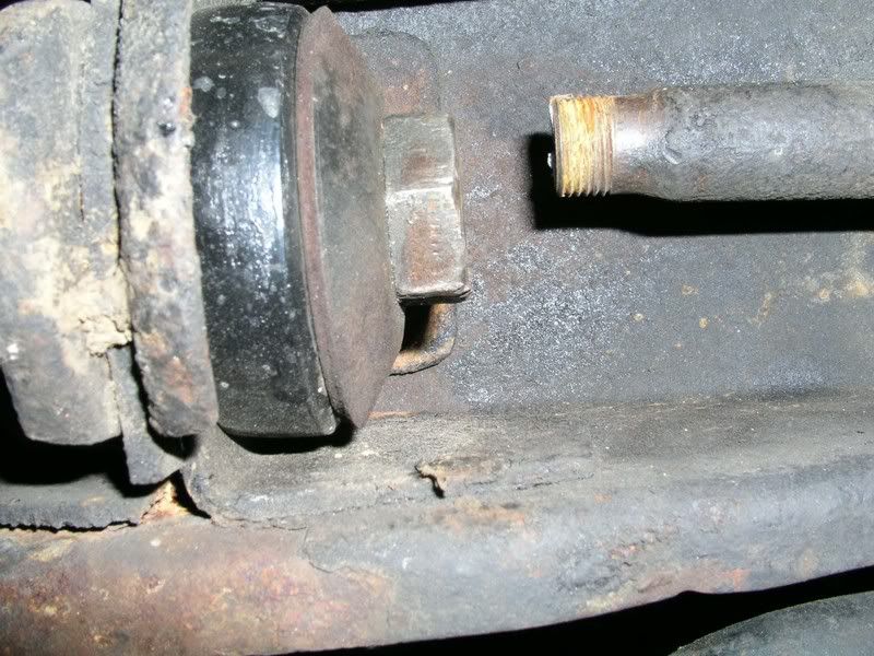
This is the result of running poly bushings on an original 50 year old strut rod then tightening the cr_p out of the nuts to compress the sh _t out of the bushings then running the washer with the curve facing them which increases the compression force on the outer edges of the bushing in both a static position and during the lower suspension arms travel.
Don’t overtighten urethane bushings and don’t run the curved washer with the curve facing inwards on urethane bushings.
Last edited by barnett468 (2/19/2015 6:53 PM)
Offline
I would never thought when I started this post, it go this long. Does anybody have a link to torque specs for the front suspension members. Somebody linked info for 65/66, but mine is a 67 and I didnt know if those specs are the same.
Offline
kdgt500 wrote:
I would never thought when I started this post, it go this long. Does anybody have a link to torque specs for the front suspension members. Somebody linked info for 65/66, but mine is a 67 and I didnt know if those specs are the same.
Look in the Mustang shop manual. They are all there. Mine is hidden out in the garage right now and is well thumbed. The torque specs for the strut to lower arm is 55-70 and for the bushings it is 40-55. That is for a 66, but since the suspensions are virtually identical, you will not go far wrong with those.
REMEMBER!!! When posting a question about your Mustang or other Ford on this forum, BE SURE to tell us what it is, what year, engine, etc so we have enough information to go on. |