FYI FORD - MustangSteve's Ford Mustang Forum
The Internet's Most Knowledgeable Classic Mustang Information
IF YOU HAVE A QUESTION ABOUT CLASSIC FORD MUSTANGS, YOU HAVE COME TO THE RIGHT PLACE!
MustangSteve has over 30 years of Mustang experience, having owned 30 of them and restored several others. With the help of other Mustangers, this site is dedicated to helping anyone wanting to restore or modify their Mustang.... THERE ARE NO DUMB QUESTIONS!!!!!
Visit MustangSteve's web site to view some of my work and find details for:
FYIFORD Contributors' PICTURES - Power Brake Retrofit Kits for 65-66 Stangs - Classic Mustang FAQ's by MustangSteve - How to wire in a Duraspark Ignition - Mustang Ride Height Pictures and Descriptions - Steel Bushings to fit Granada Spindles to Mustang Tie Rods - Visit my EBAY store MustangSteve Performance - How to Install Granada Disc Brakes MustangSteve's Disc Brake Swap Page - FYIFORD Acronyms for guide to all the acronyms used on this page - FYIFORD Important information and upcoming events

You are not logged in. Would you like to login or register?

9/24/2016 4:32 AM  #26


Re: t5 tailshaft bushing

 it's funny you guys bring up the damper or whatever it's called because I was talking yesterday with a buddy who builds hotrods and he brought up the same thing. I will look into that ,willing to try anything.i don't recall having the vibration with the c4 or when it was a 3.10 open but then again didn't put the car on the highway until the t5 was in it. 


9/25/2016 9:41 AM  #27


Re: t5 tailshaft bushing

I installed my dog bone weight on the 8.8 rear yesterday to see if it would help with vibrations I was getting above 65-70. It was noticeably smoother up to 75. Still vibrates at 80 but I have a header that is slightly touching the passenger side shock tower and need an alignment. Then disaster struck, I'll start a new thread for that.


9/25/2016 12:34 PM  #28


Re: t5 tailshaft bushing

can someone post a pic of this dogbone so I know what i'm looking for or is there a certain name for it?thanks

     Thread Starter
 

9/25/2016 2:05 PM  #29


Re: t5 tailshaft bushing


9/25/2016 2:47 PM  #30


Re: t5 tailshaft bushing

my diff does not have that mounting holes is there one that will mount to a '57 ford 9"?thanks for the pic.

     Thread Starter
 

9/25/2016 3:17 PM  #31


Re: t5 tailshaft bushing

Steve-G wrote:

I had to remove it for clerance. Also had to cut off the mounting tabs. If you can leave it. I would. I did go back and put the the one back on the t5.

 
SteveG what is the one on the T5? Do you have a pic?


9/25/2016 4:01 PM  #32


Re: t5 tailshaft bushing

Cj pony has a video on putting a 8.8 into a classic Mustang. They say you don't need it with low gears like 3.73. They do show it in the video.


9/25/2016 6:36 PM  #33


Re: t5 tailshaft bushing

The idea that you don't need the dogbone with gears numerically higher than stock is basically folklore.  The engineering paper I recently read, authored by the drivetrain engineer from Ford during the period the Fox cars were built, said the purpose of the dogbone was to dampen a specific harmonic that caused an adverse interaction with the driveshaft and lead to premature u-joint failure.  This also explains why so many people have claimed they removed the dogbone without ill effect.  There could be no real felt effect, as that was not its intended purpose.  The vibration it may dampen on a Fox car can also be changed when things like springs, lower control arms, even the exhaust is changed from stock.  I mean, how many Fox cars are still rolling around with all their stock parts?  I'm thinking none. 

Then, when swapping the rear into another vehicle that now uses leaf springs, who's to say it would even do anything?  In a Fox car I would not remove it, but on an early Mustang with a swapped in 8.8 you could run without it and if you encountered a vibration it could always be put back on, so long as there's clearance for it under the car. 

The other issue is that the dogbone relies on rubber bushings which as far as I can find are NLA.  Mine are in decent shape, still pliable, though some minor cracks here and there.  27 years under a car will do that to a bushing.  But my point is, what happens when the bushings fail or become unsafe?  With failed bushings it certainly isn't going to do its job, and if the bolts or washers were to rust through the thing could literally fall off. 

As for a dogbone on rears other than the 8.8, I've never seen anything similar on a 9".  Trying to add something like this would likely be impossible without millions of dollars in testing equipment, design software, and at the very least a serious understanding of harmonics. 


9/26/2016 7:31 AM  #34


Re: t5 tailshaft bushing

While we're discussing vibrations and factory attempts to counteract them... When I pulled my aluminum explorer driveshaft that I swapped into my mustang I noticed that the explorer slip yoke had what appeared to be some sort of harmonic balancer/dampener on it.  I was intrigued by this and wanted to try it behind my T5.  Unfortunately it wasn't a 28 spline yoke, so no-go.  I wonder if someone makes one with 28 splines...and if it would help.  Of course, I suppose it could also make things worse...

Edit... This is not a pic of the explorer yoke I have, but it shows the kind of thing I'm talking about. (the one on the far right)

Last edited by Michael H. (9/26/2016 7:45 AM)


9/26/2016 8:18 AM  #35


Re: t5 tailshaft bushing

I've seen those before as well, and they are a vibration damper.  I think the trick is that they are designed for a specific vehicle though.  I would bet, as its on the tranny end that that is designed to dampen a vibration caused by the automatic trans in the Explorer.  Every time I've seen one of those its been in a vehicle that has an auto tranny. 


9/26/2016 8:23 AM  #36


Re: t5 tailshaft bushing

Yep.  The driveshaft was from an explorer with automatic transmission.  I don't suppose anyone makes one for a T5?


9/26/2016 8:39 AM  #37


Re: t5 tailshaft bushing

Not that I ever recall seeing, you might try contacting one of the big driveshaft shops and seeing if there's a 28 spline yoke available with that type of damper.  I seem to remember my buddy's Lightning had one of those on the stock driveshaft, which was aluminum.  I had a steel shaft made for it after he threw the shaft due to a failed rear u-joint that I told him was going bad for like a year.  It bent the ear on the aluminum shaft, so it was junk and he was too cheap to just buy a new one from Ford.  I will say though, the truck was a lot smoother with the steel shaft. 


9/26/2016 4:29 PM  #38


Re: t5 tailshaft bushing

ok so I couldn't leave this alone.i  blocked the front wheels jacked up the rearend and started doing some tests.with wheels and drums off, less vibratition,then wedged wood in the exhaust and seeming no vibration(on jack stands).took the wheels down to my buddy and balanced them again,to my surprise they were off(kinda got giddy thinking this would be the answer).put everything back together,on stands it seemed better,then the road test and STILL A VIBRATION ! comes in about 60mph and very noticeable at 70mph.i forgot to mention that when I did the t5 and rebuild of the 3rd member I also bought new backing plates drums and drum assembly from quickperformance.can drums be out of balance?  

     Thread Starter
 

9/26/2016 6:29 PM  #39


Re: t5 tailshaft bushing

I pulled the driveshaft from my 89 Lincoln Mark VII 5.0 HO today.  It has AOD tranny, and the same yoke fits a T5.  The driveshaft measured 50.5" center to center of the u-joints and it has that dampner on the front of it.


Money you enjoy wasting is NOT wasted money... unless your wife finds out.
 

9/26/2016 7:01 PM  #40


Re: t5 tailshaft bushing

Drums can be out of balance.  The best balance job is to have the tires balanced on the car.  Shops used to do that, but I haven't seen one in a long time.  That way they could account for the imbalance in things like the brakes.  Trouble is I think that once you rotate the tires, or even if you put the wheel back on, but don't get the studs in the same holes you've thrown the balance off.  So your best bet is probably to try and neutral balance the drums.  Drums used to come balanced, you'd often see weights welded to them to correct the balance. 


9/27/2016 5:08 AM  #41


Re: t5 tailshaft bushing

Regarding the use of the "dog bone", one consideration for us performance/handling nuts is unsprung mass. I like a bit of a heavy rear, just not on my car. ;)

I went through a similar vibration problem and found mine was two-fold due to the engine/trans being slightly out of line in both planes (horizontal & vertical). Mine was due to using an engine plate & custom trans mount, along with stuffing an oversize engine in the car, necessitating moving stuff around. I worked out a way to figure out where the rear end was in relationship to the front wheels and engine/trans centerline so that I could get everything lined up properly. I was surprised to find that there was enough 'give' in the leaf spring isolators to allow the rear axle to be pointing off to the drivers side just under an inch at the front wheel centerline. All I had to do was loosen the rear end up and using a block of wood and a five poiund hammer I bumped the shock mounts 1/8" (fwd. on drivers, rwd. on pass), clamped it back together and took my measurements to find that it was only out 1/8" at the front (to drivers side). I have left it at that point for now. I did have to recenter the steering afterward (did a full alignment for good measure) as it was off now that I was aiming in the right direction!

Big improvement! Just rolling the car out of the garage was noticeably easier in that I could push the car further out before it stopped in the driveway (slight incline). Now that I knew where the pinion was pointing I realigned the engine and trans to get them squared (parallel) with the rear end. Once that was done I then adjusted my pinion so that it was .5 degree below the engine/trans angle (engine/trans = 2.8 / pinion = 2.3).

The car has never had a smoother ride but I think I need to subtract .5 more from the pinion (drop it to 1.8) to get it as close to perfect as I will be able. The car is smooth at all speeds unless I power into the engine without shifting down while on a steep hill (high engine torque raising pinion too far above engine/trans angle). Let off the throttle a bit while still applying power and it smooths right out.

Winter project!

Last edited by 351MooseStang (9/27/2016 5:09 AM)


9/27/2016 7:38 AM  #42


Re: t5 tailshaft bushing

351MooseStang wrote:

I worked out a way to figure out where the rear end was in relationship to the front wheels and engine/trans centerline so that I could get everything lined up properly. I was surprised to find that there was enough 'give' in the leaf spring isolators to allow the rear axle to be pointing off to the drivers side just under an inch at the front wheel centerline.

I'm interested in this...How did you measure to find out that your rear end wasn't installed straight in relationship to the front wheels?


9/27/2016 7:39 AM  #43


Re: t5 tailshaft bushing

MS wrote:

I pulled the driveshaft from my 89 Lincoln Mark VII 5.0 HO today.  It has AOD tranny, and the same yoke fits a T5.  The driveshaft measured 50.5" center to center of the u-joints and it has that dampner on the front of it.

Does it fit your T56?  If so, I'd love the hear if it helps your vibration if you get a chance to try it.


9/27/2016 10:00 AM  #44


Re: t5 tailshaft bushing

Michael H. wrote:

351MooseStang wrote:

I worked out a way to figure out where the rear end was in relationship to the front wheels and engine/trans centerline so that I could get everything lined up properly. I was surprised to find that there was enough 'give' in the leaf spring isolators to allow the rear axle to be pointing off to the drivers side just under an inch at the front wheel centerline.

I'm interested in this...How did you measure to find out that your rear end wasn't installed straight in relationship to the front wheels?

This is called "thrust angle" in alignment speak.  If you have a long enough length of something straight like heavy angle iron you can support in on 4x4 blocks or something similar and push it tight to the tire sidewalls in the rear and see if it touches the sidewall on the front tire.  Its possible that the front and rear track widths are different, so you can measure the front and back distances on the front or rear tire and see if they are the same, repeat this for the other side and compare.  Now, toe will affect this, so if you have some toe one way or the other expect the measurements to be off by a slight amount (1/16" at most).  Its sounds pretty crude, but this is actually fairly accurate.  I've used the same procedure to set the toe in my car and it worked great. 


9/28/2016 12:28 AM  #45


Re: t5 tailshaft bushing

Michael H. wrote:

I'm interested in this...How did you measure to find out that your rear end wasn't installed straight in relationship to the front wheels?

TKOPerformance wrote:

This is called "thrust angle" in alignment speak.  If you have a long enough length of something straight like heavy angle iron you can support in on 4x4 blocks or something similar and push it tight to the tire sidewalls in the rear and see if it touches the sidewall on the front tire.  Its possible that the front and rear track widths are different, so you can measure the front and back distances on the front or rear tire and see if they are the same, repeat this for the other side and compare.  Now, toe will affect this, so if you have some toe one way or the other expect the measurements to be off by a slight amount (1/16" at most).  Its sounds pretty crude, but this is actually fairly accurate.  I've used the same procedure to set the toe in my car and it worked great. 

Close! "Sharks with frickin laser beams attached to their frickin heads"... actually, lasers without the sharks and with a standoff that I made that goes off of the wheel rim and projects a line to the front of the vehicle. Sorry, we just got back from celebrating our 30th anniversary at the local Irish pub  (wife's choice) and the white Russians are double sized... ;)

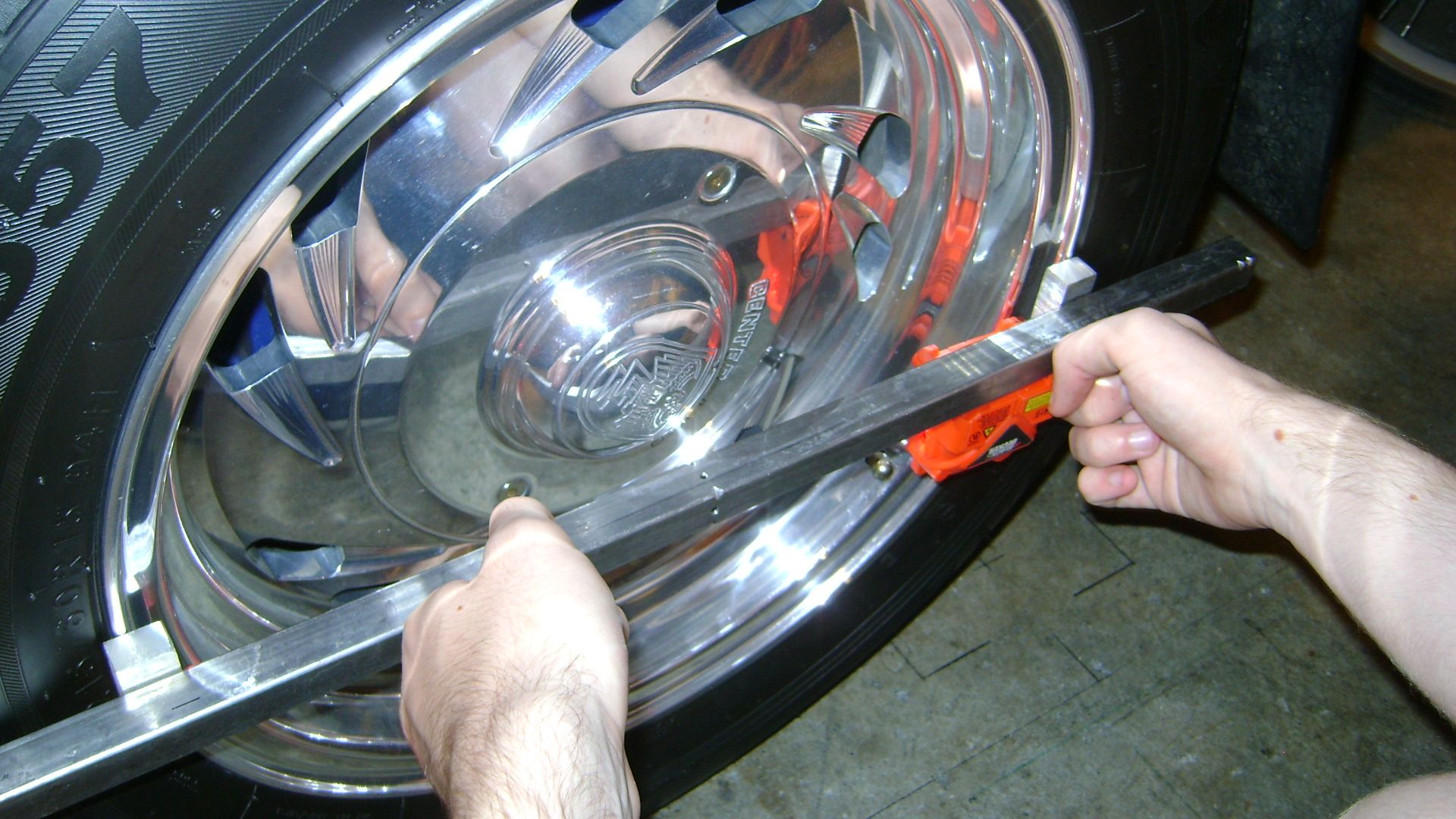
Long story short, I took a 25" length of 3/4" square mild steel tubing and mounted two 1/2" thick rectangles of aluminum  to it, spacing them 15" apart (wheel size). The aluminum pieces go up against opposite sides of the wheel rim with the steel tubing running across the middle of the wheel. I used a 1/2" standard to mark and scribe lines lengthwise across the top and bottom of the tubing. The fun really began when I had to find a laser that could project a line from a high point down to the ground and to the front of the vehicle.

The above was the easy part... The problems began when I found that the line projected by the laser I chose (Black & Decker BDL-200S) wasn't truly vertical. That means that any line projected from a higher point (center of rim) to a lower point (ground) wasn't true. In the case of the first laser I bought, the vertical line was off 1.5 degrees clockwise (slightly past noon at the top and slightly past 6 at the bottom). So if I fired that laser from the center of the rear wheel towards the ground at the front of the car, the line at the front of the car wasn't where it was supposed to be.

To zero-in the laser I squared a crosshair target on a wall in my garage across from a work bench and leveled a plate on my bench so I could mount the laser on it and find out how far off from vertical it was. Once I had that information I used a flat plate and sandpaper to true the base of the B&D laser so that it would be at the true vertical when placed on the flat plate. Once I had that zeroed in I ran into another problem; the magnetic base for the laser is as weak as Old Milwaukee beer. I think if I farted loud it would fall off of whatever metal it was attached to. I noticed that the magnet for the unit was at the bottom of the battery area and that it was a precious metals magnet like those used in computer hard drives. Since I work in computers, I have toms of those magnets around and added one to the magnet already inside the B&D unit. Bingo! It glues itself to steel great and now I can mount it to my Wheel standoff and flip it upside down without it moving or falling off. Now that B&D laser is actually useful!

Here is a pic of the laser held against the rear wheel (use bungee cord if assistant son is unavailable!):


What I did to check the rear alignment was to first level the floor in the garage where the car would be parked (using aluminum plates & a water level I made). Once the car was positioned and level, I aimed the drivers wheel straight forward (true to the rear wheel) and taped a paper 'target' to the floor centered alongside the front wheel. I then took my wheel standoff and using a plumb bob, I took a drop measurement at the center of the front wheel (ending up 1.262" from the outer wheel rim) from the outside of the standoff. I then marked the spot with an ink X centered over the bob drop point and went and then did the same thing on the passenger side.

With the target on the floor, plumb bob point marked and the laser projecting forward from the rear wheel, you get this on the floor target at the front wheel:


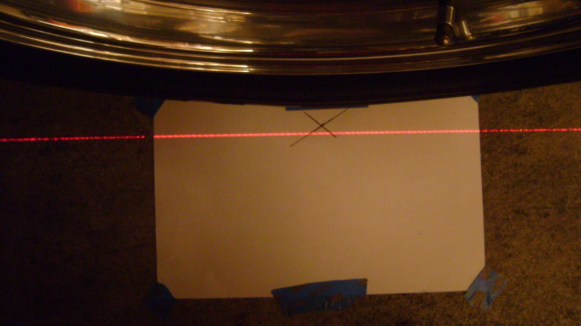
I mark three dots, spaced apart and centered on the laser line, across the target and use a straight edge to trace a line so I can measure the distance between my bob drop point and the line from the rear end. Do the same thing on the other side, take your measurements and compare the spacing. Checking my notes, I'm only out 3/64" (slightly to drivers side), which is good enough for the moment (and beats how far it was off by a mile). One other thing I noted that shows me it rolls with less resistance is a hill in town here that I coast down in second gear (off the gas) at 25 MPH. Now I coast down it at 30 and I noticed it right away because the street is 25 MPH and the local cop shop is right there too. Darn, now I'll have more brake wear! ;)

Once I knew where the rear end was pointing I was able to work out where the pinion was aiming, allowing me to fully align the powertrain. Note: I did not level the car or do any prep for these shots so the marks are not accurate but still representative of how it works.

Last edited by 351MooseStang (9/28/2016 12:31 AM)


9/28/2016 1:31 PM  #46


Re: t5 tailshaft bushing

Excellent write up 351MooseStang!  Thank you!


Board footera


REMEMBER!!! When posting a question about your Mustang or other Ford on this forum, BE SURE to tell us what it is, what year, engine, etc so we have enough information to go on.