FYI FORD - MustangSteve's Ford Mustang Forum
The Internet's Most Knowledgeable Classic Mustang Information
IF YOU HAVE A QUESTION ABOUT CLASSIC FORD MUSTANGS, YOU HAVE COME TO THE RIGHT PLACE!
MustangSteve has over 30 years of Mustang experience, having owned 30 of them and restored several others. With the help of other Mustangers, this site is dedicated to helping anyone wanting to restore or modify their Mustang.... THERE ARE NO DUMB QUESTIONS!!!!!
Visit MustangSteve's web site to view some of my work and find details for:
FYIFORD Contributors' PICTURES - Power Brake Retrofit Kits for 65-66 Stangs - Classic Mustang FAQ's by MustangSteve - How to wire in a Duraspark Ignition - Mustang Ride Height Pictures and Descriptions - Steel Bushings to fit Granada Spindles to Mustang Tie Rods - Visit my EBAY store MustangSteve Performance - How to Install Granada Disc Brakes MustangSteve's Disc Brake Swap Page - FYIFORD Acronyms for guide to all the acronyms used on this page - FYIFORD Important information and upcoming events

You are not logged in. Would you like to login or register?

5/18/2021 1:38 PM  #1


3G alternator wiring issue RESOLVED

I made a post a year or so ago (couldn't find it to update) where I had wired up a 3G alternator on the engine on my run stand.  The problem I was having was even though I had wired it like directed below the indicator/charge lite was not functioning properly.  When you turned the key on but before the engine started the light would come on like it should but when you started the engine the light would stay on.  If I put a volt ohm meter to the battery terminals with the engine running the measurement was 14.5V.  After verifying the wiring the general consensus here on the forum was that the regulator was not functioning properly and that is why the light was not going out.  I was given a second alternator and I put it on the engine to test it and it was having the exact same issue.  Turns out the problem was the light not the alternator.  The indicator light I was using must be an LED or not have enough resistance to trigger the alternator.  When I use a bulb in its place all functions as it should.  Just thought I would pass this on just in case anyone else was having a similar issue.


If it isn't broken...modify it anyway! http://www.DazeCars.com https://galaxieforum.boardhost.com
 

5/18/2021 3:35 PM  #2


Re: 3G alternator wiring issue RESOLVED

A resistor is your friend, Hey Daze

Tubo


If it ain't broke, I haven't modified it Yet
 

5/18/2021 5:10 PM  #3


Re: 3G alternator wiring issue RESOLVED

I do use an LED for the Alt. Light and, yes, I had the same issue.  Since I already had bored a hole for the LED I didn't want to change so I came up with a much more complex solution...whoda thunk?  I used a Bosch relay coil as the normal incandescent lamp filiment and let the relay switch the LED on when not charging.  Soon as the alternator spools up the relay drops out and the LED goes off.  Got a diagram if anyone wants.
I think the problem witih the LED is that they will fire with a relatively low potential difference.

Last edited by Bullet Bob (5/18/2021 5:11 PM)


"you get what you pay for, good work isn't cheap, and there are NO free lunches...PERIOD!"
 

5/19/2021 9:03 AM  #4


Re: 3G alternator wiring issue RESOLVED

Bullet Bob wrote:

I do use an LED for the Alt. Light and, yes, I had the same issue.  Since I already had bored a hole for the LED I didn't want to change so I came up with a much more complex solution...whoda thunk?  I used a Bosch relay coil as the normal incandescent lamp filiment and let the relay switch the LED on when not charging.  Soon as the alternator spools up the relay drops out and the LED goes off.  Got a diagram if anyone wants.
I think the problem witih the LED is that they will fire with a relatively low potential difference.

I installed an LED charge lamp per BB's diagram (LED operates via relay), works as intended.  Note that I have a GM 10SI alternator. 
I had had an incandescent light bulb w/o the relay and it worked fine until the voltage regulator started to allow the alternator to put out 18v and burned out the bulb.


65 Fastback, 351W, 5-speed, 4 wheel discs, 9" rear,  R&C Front End.
 

5/19/2021 1:32 PM  #5


Re: 3G alternator wiring issue RESOLVED

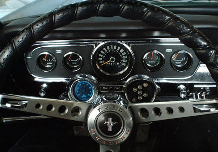
Can someone explain the 5 gauge cluster portion of picture?

I don’t get that portion.


5/19/2021 1:40 PM  #6


Re: 3G alternator wiring issue RESOLVED

Nos681 wrote:

Can someone explain the 5 gauge cluster portion of picture?

I don’t get that portion.

The regulator uses power through a resister as part of its control.  with an idiot light the actual bulb is the resister.  With an amp or volt gauge there is no bulb and thus no resister so one needs to be added.  Make sense?


If it isn't broken...modify it anyway! http://www.DazeCars.com https://galaxieforum.boardhost.com
     Thread Starter
 

5/19/2021 6:00 PM  #7


Re: 3G alternator wiring issue RESOLVED

Bullet Bob wrote:

Got a diagram if anyone wants.

I would like to see the schematic.


If it isn't broken...modify it anyway! http://www.DazeCars.com https://galaxieforum.boardhost.com
     Thread Starter
 

5/20/2021 10:23 AM  #8


Re: 3G alternator wiring issue RESOLVED

Daze wrote:

Bullet Bob wrote:

Got a diagram if anyone wants.

I would like to see the schematic.
 

My car has neither the volt meter or the two terminal ammeter.  It has the inductive ammeter.


5/20/2021 11:09 AM  #9


Re: 3G alternator wiring issue RESOLVED

Nos681 wrote:

My car has neither the volt meter or the two terminal ammeter.  It has the inductive ammeter.

I have that too. You still need some sort of resister on the I terminal.


If it isn't broken...modify it anyway! http://www.DazeCars.com https://galaxieforum.boardhost.com
     Thread Starter
 

5/20/2021 12:35 PM  #10


Re: 3G alternator wiring issue RESOLVED

Daze wrote:

Nos681 wrote:

My car has neither the volt meter or the two terminal ammeter. It has the inductive ammeter.

I have that too. You still need some sort of resister on the I terminal.

The wire on the ignition switch that goes to the "I" terminal on the alternator also is the ignition switch feed to the ignition coil.  With the engine running, and the alternator providing power, the "I" terminal will have enough voltage that will extinguish the alternator light, if installed. The resistance of the light is enough to prevent a back-feed to the ignition wire at the ignition switch that would keep power on the ignition coil and will enable the engine to continue to run with the ignition key "off".  If you do not have an alternator light, you need a resistor to prevent this voltage from feeding the ignition wire.  As indicated in the diagram, a resistor in parallel with the light will enable the alternator to function if the light burns out. 
Send a PM to me with your email and I can forward BB's LED alternator light circuit.  I did this conversion on my Mustang and it works just fine.


65 Fastback, 351W, 5-speed, 4 wheel discs, 9" rear,  R&C Front End.
 

5/20/2021 6:53 PM  #11


Re: 3G alternator wiring issue RESOLVED

BobE wrote:

Daze wrote:

Nos681 wrote:

My car has neither the volt meter or the two terminal ammeter. It has the inductive ammeter.

I have that too. You still need some sort of resister on the I terminal.

The wire on the ignition switch that goes to the "I" terminal on the alternator also is the ignition switch feed to the ignition coil.  With the engine running, and the alternator providing power, the "I" terminal will have enough voltage that will extinguish the alternator light, if installed. The resistance of the light is enough to prevent a back-feed to the ignition wire at the ignition switch that would keep power on the ignition coil and will enable the engine to continue to run with the ignition key "off".  If you do not have an alternator light, you need a resistor to prevent this voltage from feeding the ignition wire.  As indicated in the diagram, a resistor in parallel with the light will enable the alternator to function if the light burns out. 
Send a PM to me with your email and I can forward BB's LED alternator light circuit.  I did this conversion on my Mustang and it works just fine.

I don't know how the internal of the 3G works but this is what I kinda of thought. You put +12 volts on one side of the light bulb form the ignition switch, the other side is tied to ground inside the 3G and the light bulb lights. Now when the 3G fires up the internal ground goes away and maybe goes to +12 volt and the light goes out. Now if there isn't a light bulb or resister; the ignition wire is +12 volt, the 3G is ground, you will blow a fuse or burn up a wire. This is just a guess because I don't know the internal of the 3G but what BobE says makes sense too.


If this forum can't fix it, it isn't broke.
 

5/21/2021 2:48 PM  #12


Re: 3G alternator wiring issue RESOLVED

wsinsle wrote:

BobE wrote:

Daze wrote:


I have that too. You still need some sort of resister on the I terminal.

The wire on the ignition switch that goes to the "I" terminal on the alternator also is the ignition switch feed to the ignition coil.  With the engine running, and the alternator providing power, the "I" terminal will have enough voltage that will extinguish the alternator light, if installed. The resistance of the light is enough to prevent a back-feed to the ignition wire at the ignition switch that would keep power on the ignition coil and will enable the engine to continue to run with the ignition key "off".  If you do not have an alternator light, you need a resistor to prevent this voltage from feeding the ignition wire.  As indicated in the diagram, a resistor in parallel with the light will enable the alternator to function if the light burns out. 
Send a PM to me with your email and I can forward BB's LED alternator light circuit.  I did this conversion on my Mustang and it works just fine.

I don't know how the internal of the 3G works but this is what I kinda of thought. You put +12 volts on one side of the light bulb form the ignition switch, the other side is tied to ground inside the 3G and the light bulb lights. Now when the 3G fires up the internal ground goes away and maybe goes to +12 volt and the light goes out. Now if there isn't a light bulb or resister; the ignition wire is +12 volt, the 3G is ground, you will blow a fuse or burn up a wire. This is just a guess because I don't know the internal of the 3G but what BobE says makes sense too.

The ignition switch wire provides the +12v to the light bulb (and parallel resistor) and to the alternator field (rotor) and to the stator through a diode bridge (the other side of the diode bridge is grounded).  The diode bridge is necessary to convert AC produced by the alternator to DC used in the car. 
Once the alternator is spinning and providing power, the stator provides power to charge the battery and drive the accessories.  The stator and field are connected to the electronic regulator that also will back feed the ignition switch wire (bulb and resistor).  The presence of + voltage on both sides turns off the bulb. 
If one has an MSD box, a diode is installed in line with the bulb to insure the MSD box does not continue to provide ignition power.  If one is not using a light, a diode should be installed to prevent the back fed voltage to the ignition switch.


65 Fastback, 351W, 5-speed, 4 wheel discs, 9" rear,  R&C Front End.
 

Board footera


REMEMBER!!! When posting a question about your Mustang or other Ford on this forum, BE SURE to tell us what it is, what year, engine, etc so we have enough information to go on.