| ||
Visit MustangSteve's web site to view some of my work and find details for: FYIFORD Contributors' PICTURES - Power Brake Retrofit Kits for 65-66 Stangs - Classic Mustang FAQ's by MustangSteve - How to wire in a Duraspark Ignition - Mustang Ride Height Pictures and Descriptions - Steel Bushings to fit Granada Spindles to Mustang Tie Rods - Visit my EBAY store MustangSteve Performance - How to Install Granada Disc Brakes MustangSteve's Disc Brake Swap Page - FYIFORD Acronyms for guide to all the acronyms used on this page - FYIFORD Important information and upcoming events |
Offline
James, I have been told, and I have heard on this forum that Ford included the diode internal on later model relays.(Fox, Thunderbird, F150...) I played with the one I have and can't measure it due to it being in parallel with the solenoid assuming it is there. So a quick trip around the WWW and I found a great write up that explains the theory and a schematic. I can't seem to cut and paste it here so... here is the link, check it out. It is for a cessna application, but you will see that it applies here directly.
The Fox schematic does show a diode internal to the starter relay across the solenoid. If this is the diode that you are referring to then I would say you are covered if you are using the later Ford relay. If you are controlling the relay with a logic circuit you may want additional protection for the circuit.
Last edited by KStang (11/29/2013 11:20 AM)
Offline
Thanks for the link explaining how the diode works. It printed out well!
Have saved it for later use. Again, thank you
Howard
Offline
If you are using an original solenoid 'S' terminal to Gnd. That is how the coil is wired inside. If you are going to use an extra relay as in your diagram, a diode across the relay coil wll help save the ignition switch. Some relays also come with the diode built into them just like the Fox solenoid. Keep in mind these diodes are to help protect the contacts of the extra relay or ignition switch, they do not protect the contacts in solenoid.
Offline
ok, added in the diode locations - one of your electronic whizs give this a check and tell me if I need more/less/move them.
Offline
Diodes need turned around. Does the PMGR have a built in diode, if not one should be there. Diodes should be as close to the coil as possible.
Offline
James
I was reading another post and had a few thoughts on your setup. One thought is there is no way of knowing if one of the solenoids stick. Saythe rear solenoid sticks, contacts weld themselves shut, the cable to the front would remain hot at all times. This would defeat the whole purpose of your setup. One idea was to put a small indicating light off of the large cable to the front. This would verify the cable dead when not in the start position. The light bulb is tested each time you start the car.
Another thought would be get rid of the 30 Amp relay. Use a toggle switch to pick up the rear solenoid, only to be turned on during starting, then turned off. Use the key for the PMGR. The idea here is, if you turn on the toggle switch and the engine cranks without the key on, the solenoid in the PMGR is stuck.
Just thought I would through out a couple more ideas for you to think about.
Offline
Just joined the forums here as I have been researching this topic and wanted to get some feedback on idea that is a small twist on the above diagrams. I posted the same on VMF for those that visit there as well.
While the above diagram will work great, my goal is to use the one large awg power wire for both starter circuit and main power for the car. Could we kill 2 birds with one stone by using the trunk mounted solenoid to act as a by-pass for a mega-fuse only when engaging the starter? This would also allow the alternator to charge the battery through the same large awg wire.
What if did the following:
1) Run a large awg power cable from battery to a distribution post in the engine bay with say a 150 amp mega fuse in-line near the battery in the trunk.
2) All other car electrical needs tap into the distribution post in the engine compartment, including the cable from the alternator.
3) A separate starter relay would trigger both the trunk mounted and PMGR starter mounted solenoids, just like in the diagrams above.
4) When engaged, the trunk mounted solenoid simply bypasses the in-line mega fuse only when starting the car. In theory the mega fuse will not blow because the trunk mounted solenoid bypassing the fuse provides the least path of resistance to the starter. When the key springs back off of 'Start' all power flows through the mega fuse again protecting the main power source. And ... it provides the same large awg cable back to the battery for your alternator to charge the battery.
Again this is just an idea that might be riddled with other issues or misunderstandings on my part but that is why I posting the thought rather than just doing it. If it works than you can have 1 large awg cable from the trunk to the front of the car to be used for starting and for car power, but it is also fused for fire safety.
Rob
Offline
First off welcome Rob. Just so I’m understanding what you are saying; when you turn the key to start the car you’ll pick up the solenoid in the mini starter and the solenoid in the trunk. The one in the trunk shorts around the mega fuse so it won’t blow. I really like you’re thinking, just not sure if it would work. The mega fuse will have some very low internal resistance but the contacts to the solenoid also have some very low resistance. When you start the car the current going to the starter will split paths between the solenoid contacts and the mega fuse proportionally to their resistance. Probably about half and half. Not knowing how much current the starter draws, it may or may not work.
Offline
You got it. I have the same question you presented so I suppose I can try it out and see. I will post a diagram as well.
Offline
I created a quick diagram as it is much easier with a picture. I made one change to the logic, which is to use the 'I' terminal on the trunk solenoid to trigger the PMGR solenoid. Otherwise, if the trunk solenoid failed, the Bosch relay would still engage the PMGR starter, but it would draw all the current through the mega fuse and likely blow it. Using the 'I' terminal ensures the starter will only crank if the trunk mounted solenoid is operational.
Offline
JamesW wrote:
ok, added in the diode locations - one of your electronic whizs give this a check and tell me if I need more/less/move them.
JamesW, No need to get complicated... I think you had the right idea in the first diagram (post #15). Signaling both solenoids from one source will work fine. Just add a fused wire from the battery to the alternator and you'll be good. It's really no different than normal except that you're adding a solenoid in the trunk to keep full-time voltage off of the long run of un-fused starter wire.
Offline
rvh345 wrote:
I created a quick diagram as it is much easier with a picture. I made one change to the logic, which is to use the 'I' terminal on the trunk solenoid to trigger the PMGR solenoid. Otherwise, if the trunk solenoid failed, the Bosch relay would still engage the PMGR starter, but it would draw all the current through the mega fuse and likely blow it. Using the 'I' terminal ensures the starter will only crank if the trunk mounted solenoid is operational.
I don't know if this would work well. Usually with the PMGR starter the primary starter terminal ("battery") goes to the battery post on the solenoid and a new 12AWG wire goes from the rear solenoid post (the one that used to feed the starter) to the solenoid on the starter. Some people have fed both the high current ("battery") starter terminal and the starter solenoid terminal from the rear solenoid post to prevent accidental shorts at the starter (or you can also jumper them together - see the altered diagram below). I don't know whether the I terminal on the solenoid has enough current capacity to reliably operate the solenoid at the starter - it's usually only used to power the ignition coil and a couple of other things that have relatively small current draws through a 14 or 16 AWG wire.
I also think it would be more efficient to power the Bosch-style relay switching contact from the solenoid rather than running wires all over the place to get to it.
Last edited by John Ha (6/04/2014 3:44 PM)
Offline
This is the final configuration I installed.....
My main goal was to do away with a large gage hot wire running the length of the car. This setup has been installed for several months and works perfectly.
Offline
John Ha wrote:
Some people have fed both the high current ("battery") starter terminal and the starter solenoid terminal from the rear solenoid post to prevent accidental shorts at the starter (or you can also jumper them together - see the altered diagram below).
The concern I have with this approach is the backfeed from the starter spin down can keep power to the solenoid and cause starter run on.
John Ha wrote:
I don't know whether the I terminal on the solenoid has enough current capacity to reliably operate the solenoid at the starter
Not sure either, but if not a simple relay will solve that. I just want to ensure the starter will not engage unless the trunk solenoid is operational.
John Ha wrote:
I also think it would be more efficient to power the Bosch-style relay switching contact from the solenoid rather than running wires all over the place to get to it.
The entire purpose of my proposed alteration is to reduce the overall number of wires needed and to maintain a large gauge wire from the alternator to charge the battery. The diagram is certainly not to scale, but just to demonstate connections.
I appreciate your taking time to provide feedback, Their are certainly multiple ways to solve this. JamesW solution seems to work well, so at least I know I have that to fall back on.
Rob
Last edited by rvh345 (6/04/2014 8:22 PM)
Offline
James, I like your final set up. Did you happen to fuse the alternator output? I don’t feel this does any good unless you fuse the battery, which you did.
Rob, one advantage I see in your set up is the battery is being charged from a larger wire. There would be very little voltage drop between the alternator and the battery. Someone else on here was having a problem with that, don’t remember what the fix was. The disadvantage I still feel is blowing that fuse. Even if it works now, over time the contacts in that solenoid will pit and get dirty, which will raise the resistance of the contacts. If I was to use that set up, I would keep a spare fuse or a 12 gauge jumper handy.
One other thing do you feel you need the relay if only picking up the one solenoid with the key?
Offline
wsinsle - Carrying the spare meag fuse is certainly a good idea, but am hopeful that it will not blow over time. Even if the contacts wear over time I would think it would still not create a resistance level that yield enough of a current to blow a 150 amp mega fuse.
I like your revision, as I agree that a relay from the ignition switch is likely redundant. Per a previous post, I am not sure if the 'I' terminal can handle the PMGR solenoid current required, so we might want a relay on that circuit. Anyone know what that 'I' terminal is rated at?
Rob
Offline
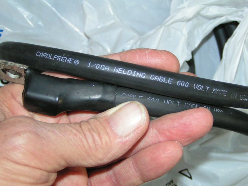
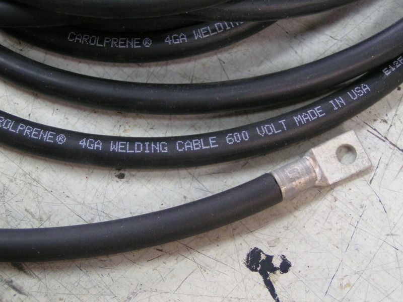
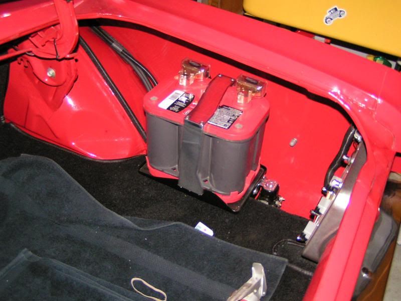
I have talked to few people who have had issues with trunk mounted batteries. It seems that in most cases the cables that they used to to starter were too small for the task of handling the current required to spin the engine over. Welding cable sourced from wholesalers is a far better choice than the “one size fits all” kits that are offered by places like Summit. the welding cables are extremely flexible and can be routed just about anywhere. Don’t waste your money on a separate ground cable from the trunk mounted battery to the front of the car or engine, using a heavy ground strap or cable at the rear frame is just as good . The Mustang body is an excellent conductor for grounds.
I used #4 for the charging system and 1/0 cable to the starter.
Offline
Rudi - Excellent point! I have 2/0 weleding cable running from the trunk to the front. In addition to being better cable the fleixibility it provides makes it easy to route. Braided grounding strap to the body is also planned and agree that the body makes an excellent ground. Your setup looks great. Very clean install. -Rob
Offline
Rob the weakest link for the ‘I’ terminal is inside the solenoid. The wire between the large contact and the 'I' terminal. Because the wire moves with the contact, it would have to be a fine multi strain wire. I would also think it would not be too small of a gauge or it would eventually break. No way to know for sure unless you open one up.
I also agree with Rudi, spend your money on the positive wire not the ground. Make sure you are grounding to bare solid metal and not paint. Use wire grease between the terminals and body. I would place a braided ground near the starter, alternator and one from the rear of the heads to the body.
Offline
Confirmed on the grounding strap. Neg post of the battery directly to the body in the trunk. Other straps from head to body, etc. I found this write-up that I thought was useful and it has some great ideas on the grounding straps, including the use of the wire grease.
I will give the proposed solution a try and I will update the diagram if it ultimately works. I will use a relay off of the I terminal, just to be safe. Not sure I will get to it this weekend, but I will report back.
I appreciate all the dialogue and feedback on the idea.
Rob
Last edited by rvh345 (6/05/2014 11:04 AM)
Offline
Here is a couple of questions to think about: 1) Where did the factory bolt the other end of the battery ground cable? and why? 2) What is the ground path from the starter back to the battery with the battery ground bonded to the trunk floor? 3) What is the relative conductivity of 1/0 welding cable vs the 46 year old 19 ga sheetmetal the car is made of?
Offline
wsinsle wrote:
James, I like your final set up. Did you happen to fuse the alternator output? I don’t feel this does any good unless you fuse the battery, which you did.
Yes, I used the MAD electrical 'start 'em up' kit for all the small wiring of the relo. The alternator feed is an 8 gage wire running into a 12 gage fuse link at the solenoid. The starter cable is 1-0 welding cable.
Offline
All - Just an update on this as I finally was able to get it wired up and tested. Initial tests indicate that it is working as expected. I took some amp readings it appears that the full amperage draw gets split along the paths. Here are the readings I am getting:
1) Cable from the battery to the mega fuse - Initial crank 325 amps quick drop to 170 amps
2) Cable to/from the solenoid (the bypass of the mega fuse) - Initial crank 115 amps drop down to 75 amps
3) I removed the mega fuse and replaced with a 6 awg wire temporarily so I could try and simulate what might be going through the fuse. I received the same readings as #2 above.
I am running 175 amp mega fuse and I ran several long engine cranking tests of about 10 seconds each and all worked great.
Updated diagram is below.
Last edited by rvh345 (7/28/2014 2:08 PM)
Offline
rvh345 wrote:
All - Just an update on this as I finally was able to get it wired up and tested. Initial tests indicate that it is working as expected. I took some amp readings it appears that the full amperage draw gets split along the paths. Here are the readings I am getting:
1) Cable from the battery to the mega fuse - Initial crank 325 amps quick drop to 170 amps
2) Cable to/from the solenoid (the bypass of the mega fuse) - Initial crank 115 amps drop down to 75 amps
3) I removed the mega fuse and replaced with a 6 awg wire temporarily so I could try and simulate what might be going through the fuse. I received the same readings as #2 above.
I am running 175 amp mega fuse and I ran several long engine cranking tests of about 10 seconds each and all worked great.
Updated diagram is below.
Interesting concept. Got any pics of the trunk end?
Offline
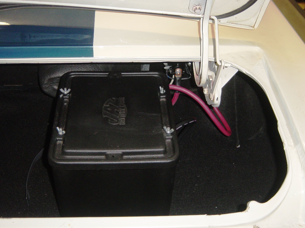
Here is a quick pic of the install in the trunk (note - the pink wire at the top of the pic is unrelated, just there because it was a good routing spot). Also, I have not yet concluded that this is a done deal, as I have only tested the few times since install this last weekend. I will certainly carry a spare fuse for a while just to be sure it is sound, but so far it looks promising.
Rob
REMEMBER!!! When posting a question about your Mustang or other Ford on this forum, BE SURE to tell us what it is, what year, engine, etc so we have enough information to go on. |