| ||
Visit MustangSteve's web site to view some of my work and find details for: FYIFORD Contributors' PICTURES - Power Brake Retrofit Kits for 65-66 Stangs - Classic Mustang FAQ's by MustangSteve - How to wire in a Duraspark Ignition - Mustang Ride Height Pictures and Descriptions - Steel Bushings to fit Granada Spindles to Mustang Tie Rods - Visit my EBAY store MustangSteve Performance - How to Install Granada Disc Brakes MustangSteve's Disc Brake Swap Page - FYIFORD Acronyms for guide to all the acronyms used on this page - FYIFORD Important information and upcoming events |
Offline
The car is a '62 Falcon two door wagon with a 289, the battery is staying in the engine bay.
I read James W's post regarding his PMGR install with a trunk mounted battery and gleaned a lot from it , but I have a few questions on my mind yet and was hoping you folks would share your thoughts.
I was going to wire mine exactaly as James W had except wondered if the main fender apron mounted starter relay is really the way to go. Makes plenty of sense with a trunk mounted battery, but since I have a short cable run I'm considering wiring the starter directly to the battery with a fuse or circuit breaker.
I intend to use a relay with an internal diode to trigger the starter solenoid so I'm not talking about jumpering the two poles on the PMGR or anything like that, just not yet sure which way to go with the big wire. I like neat and simple and it seems it would clean things up a bit but wondered if any of you have done something similar or just flat out advise against this.
Offline
I don't have the battery in the trunk but did wire the starter directly to the battery (no fuse, just a big cable and plenty of care to ensure that it will be hard to short to ground) and then added a 12 AWG wire to the large aft terminal of the fender solenoid to trigger the starter solenoid.
I have not experienced any issue with this setup and it has consistently worked well.
Last edited by John Ha (7/11/2014 8:07 AM)
Offline
I have a wire from the battery to a terminal post, from there it goes directly to the mini starter. The wire from the start position on the key switch, goes directly to the solenoid on the mini starter. From there I use a diode to supply +12 volts to the coil during cranking. I'm thinking on going to a pertronix with 12 volt coil to avoid the diode.
Offline
wsinsle wrote:
I have a wire from the battery to a terminal post, from there it goes directly to the mini starter. The wire from the start position on the key switch, goes directly to the solenoid on the mini starter. From there I use a diode to supply +12 volts to the coil during cranking. I'm thinking on going to a pertronix with 12 volt coil to avoid the diode.
Yep!!.....did away with my original solenoid when installing my new mini starter. Because....it has its own solenoid! Why use both?.....right? Kinda like having a switch to turn on a switch to turn something on!!!!!!!!
6sal6
Offline
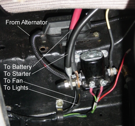
Here is a typical PMGR starter connection. The Yellow wire on the right side of the solenoid connects to the solenoid on the starter.
Offline
Thank you everyone. I think the only reason I considered a fuse or circuit breaker was to retain a positive lug for a connection point to the alt and aux, so I guess that's one reason to keep the original starter relay.
The direct connect route has me wondering about the diode hook up between the ign switch and solenoid. Does the striped or cathode end go to the solenoid post with the anode to ground? This one is confusing to me because I thought the starter grounds through the starter body and the spike would bypass the diode, Also was wondering if you went with the 1N4004 or the 1N5400.
I hear you about the switch to turn on a switch etc., action and thought the redundant relays was for voltage fly back protection, but if direct connect from ign switch to solenoid with a snubbed is a go I'd like to hear how to hook that up. I run a Mallory distributor and try to be mindful of mitigating voltage spikes. If I can go straight from battery to starter and from ign switch to solenoid with a voltage snubber that's probably the way I'll go.
Offline
OK, I misunderstood about the diode on the solenoid. WSINSLE is talking about jumping 12v to the coil while cranking.
I think I'll just wire it up the way it looks in the pic you posted James W and check for voltage spikes. I would think the solenoid would generate a voltage spike after you get off the key unless these starters have an internal diode.
Sorry if I'm being as clear as mud or over thinking this, I just don't want to fry my ignition module or do something to shorten it's service life.
Offline
I just used a terminal post to eliminate the extra solenoid.
Been thinking of making some kind of cap to cover the terminal in case I drop a tool down there.
Last edited by wsinsle (7/12/2014 5:35 AM)
Offline
wsinsle wrote:
Been thinking of making some kind of cap to cover the terminal in case I drop a tool down there.
I used a rubber terminal post cover used to cover the back of the power wire on a 3G alternator. fit just right
Last edited by JamesW (7/12/2014 7:28 AM)
Offline
I like your use of 'sealtight' to run the wiring, you should consider installing "insulated bushings" on the ends to keep the exposed wiring from being cut into and causing short to ground.
Offline
James:
That sounds like a really good idea. I need to finish the heat shrink around the wire ends and that should work.
Bob:
That was my intention to use the ends, but the Lowes were I live are always out of something when I'm doing a project. All the good hardware stores closed down. Any how, those connector are plastic so I wasn't getting to bent out of shape over them.
Thanks for the input.
Offline
wsinle - electrical supply house would be your best bet to find these. There are two types available, one is metal w/a plastic insert, the other is all plastic.
Offline
I think I will end up using either the stock starter relay or a relay of some sort to signal the starter solenoid. I can't find any good information on the pull in or holding current demand of the solenoid, I've heard anywhere from 1a to 60a. It is generally recomended to use a 12awg to connect to the solenoid stud and that guage wire is capable of more current flow than I would want going through my ignition switch regularly.
Offline
Would someone explain to me why I nee a diode on the key switch wire? I've have my mini starter wired with a battery cable direct to the solenoid and the the wire that triggered the fender mounted solenoid now triggers the solenoid mounted on the starter. GM did it that way for years. I was like Sally, why switch a switch, unless the battery is in the trunk then it makes sense! but I think a mega fuse would do just as well???
Offline
terry wrote:
Would someone explain to me why I nee a diode on the key switch wire? I've have my mini starter wired with a battery cable direct to the solenoid and the the wire that triggered the fender mounted solenoid now triggers the solenoid mounted on the starter. GM did it that way for years. I was like Sally, why switch a switch, unless the battery is in the trunk then it makes sense! but I think a mega fuse would do just as well???
You don't need a diode Terry. Mine's wired like yours.. a solenoid firing a solenoid. I wired mine that way just for convience with the original wiring. I think some folks get in trouble when they jump the power and trigger connection together on the pgmr starter...then use the original solenoid to send power both at once. That doesn't work quite right because the trigger connection receives voltage from the starter itself as it winds down and acts somewhat like a generator.
Offline
terry wrote:
Would someone explain to me why I nee a diode on the key switch wire? I've have my mini starter wired with a battery cable direct to the solenoid and the the wire that triggered the fender mounted solenoid now triggers the solenoid mounted on the starter. GM did it that way for years. I was like Sally, why switch a switch, unless the battery is in the trunk then it makes sense! but I think a mega fuse would do just as well???
As I understand it, the diode is typicaly used where a relay is used.
Mechanical relays have a coil that when energized creates an electro-magnetic field. When the circuit is opened (switched off) the voltage spikes as the field collapses. The voltage spike reduces the service life of the relay as it tack welds the contacts every time it's opened, and the spike could be detrimental to other sensitive electronics.
Last edited by Jon Richard (7/14/2014 9:22 PM)
Offline
Terry the diode is optional, it is put on some solenoid coils to help protect the ignition switch.Some solenoids have them built in. Mine is wired like yours and I didn't use one. Hoped Ford put it in the mni starter solenoid. If I was using multiple solenoids with battery in trunk, I would use them. I will say this, my Dodge truck has a contact in the ignition switch that shuts off the heater fan motor, if left on, when you turn off the key. (Same idea droping the fan motor or solenoid) I have already replaced the ignition switch twice.
Offline
Mine is overly complicated, only because I'm running EFI (wanting to avoid a spike) and I wanted to not have a 1/0 gage constant hot wire running to the trunk battery. This setup has been working well for several months now.
Last edited by JamesW (7/15/2014 6:45 PM)
Offline
I can certainly understand using a diode with EFI those computers don't like spikes!!
I thought I was missing something!
Offline
JamesW wrote:
Mine is overly complicated, only because I'm running EFI (wanting to avoid a spike) and I wanted to not have a 1/0 gage constant hot wire running to the trunk battery. This setup has been working well for several months now.
The diagram from your original post showed a diode with the 30a relay, did you omit it? I was also curious if you used the 1N4004 or did you go with a 1N5400?
I would realy like to find out what the starter solenoid pull in current is, it would help greatly to know if the relay from the ignition switch to the solenoid is needed.
Offline
Jon Richard wrote:
JamesW wrote:
Mine is overly complicated, only because I'm running EFI (wanting to avoid a spike) and I wanted to not have a 1/0 gage constant hot wire running to the trunk battery. This setup has been working well for several months now.
The diagram from your original post showed a diode with the 30a relay, did you omit it? I was also curious if you used the 1N4004 or did you go with a 1N5400?
I would realy like to find out what the starter solenoid pull in current is, it would help greatly to know if the relay from the ignition switch to the solenoid is needed.
This is the final configuration I used. Honestly I don't remember which diode because it was donated! I just hooked it up.
REMEMBER!!! When posting a question about your Mustang or other Ford on this forum, BE SURE to tell us what it is, what year, engine, etc so we have enough information to go on. |