| ||
Visit MustangSteve's web site to view some of my work and find details for: FYIFORD Contributors' PICTURES - Power Brake Retrofit Kits for 65-66 Stangs - Classic Mustang FAQ's by MustangSteve - How to wire in a Duraspark Ignition - Mustang Ride Height Pictures and Descriptions - Steel Bushings to fit Granada Spindles to Mustang Tie Rods - Visit my EBAY store MustangSteve Performance - How to Install Granada Disc Brakes MustangSteve's Disc Brake Swap Page - FYIFORD Acronyms for guide to all the acronyms used on this page - FYIFORD Important information and upcoming events |
1 of 1
Offline
Does the proportioning valve which is plumed in after the MC.........do the lines go from there to the brakes or........do they need to go back through the distribution valve that came on the 66?
thanx
6sally6
Offline
i always run my lines from the master to the dist block, then plumb the prop valve into the line running from the dist block to the rear brakes.
Offline
the distribution block is for the front brakes only in a set up that uses a Prop valve. Run the distribution block to the front to brakes then the master cylinder goes straight into a proportioning valve for the rear brakes and then from the proportioning valve to the rear
Offline
6sally6 wrote:
Does the proportioning valve which is plumed in after the MC.........do the lines go from there to the brakes or........do they need to go back through the distribution valve that came on the 66?
thanx
6sally6
Mike, IIRC you are switching from 4 wheel drum to a disc drum dual bowl power booster scarebird setup right?
If you are referring to the brass distribution block, the stock setup for that was that the MC went to that brass block and then 2 lines out to the front brakes and 1 line out rear brake lines. a total of 4 lines on that brass thing. Leave the front brake lines connected to the brass thing, and remove the rear brake line from the brass thing. Also remove the mc line from the brass thing.
with a dual bowl disc drum mc, the larger bowl should be for the discs, and a new line would go from mc to the brass distribution block, and then out to the front brakes. you will need to plug up the extra hole on the brass block with an ?asn inverterted flare? plug, since you removed the line to the rear brakes. I dont think i'm giving it the correct name.. Anyway from the smaller bowl of the mc, a new line woud go to a seperate adjustable rear prop valve which has two ports labeled IN and OUT. connect MC to IN, and then OUT to the unhooked rear brake line that was taken off the brass distribution block.
This above paragraph is one way to do it. There is another option to get rid of the brass block and the adjustable proportioning valve by getting another single fixture that will take the place of the two separate pieces. I'm pretty sure MS has a FAQ for this. I think the popular way is to get a fox combo valve which will handle both functions (distribution and Proportioning) in one piece as well as an added benefit of a third function of Metering. this would require some creativity to creating the new lines from MC to this combo valve and then to connect it to the rear brake line and the front brake lines. they do sell kits that have the valve and the lines already pre bent for you.
IIRC there are a few things to consider when deciding on which to choose.. Distribution, Proportioning, and Metering. Distributing the fluid to the front and rear brakes, Proportioning the pressure so that rear brakes get applied first but dont lock up before front brakes are applied, and Metering which eludes me at the moment... I dont recall if it meteres uneven pressure between front and rear and compensates, or somehow meters it to throw a warning light on dash in case of a leak or a low fluid condition?
Also when creating the lines, the loops of the lines are not to be higher than the mc.
Offline
steve s. wrote:
i always run my lines from the master to the dist block, then plumb the prop valve into the line running from the dist block to the rear brakes.
I don't see how that is possible if you have a dual bowl mc. The stock single bowl master had 1 line to the brass block. A drum/drum dual bowl would have two lines coming out correct? A disc/drum would also have two lines coming out.
Last edited by MarkinSC (5/25/2013 6:23 AM)
Offline
Sal, you are using the 70 style combination valve. Plumb it exactly like the diagram on my GRANADA brake installation page. DO NOT reuse the existing distribution block. I supplied the 7/16-24 tube nuts for the fittings requiring those. The 3/8" tube nuts will come with whatever tubing you buy.
Offline
'65/'66 Mustangs had single resevoir MCs. There would have been two lines coming out the front end of the original single pot MC (or least there are on the GT). One line would have lead directly to the rear brakes. The other would have gone over to a 3-port brass Tee mounted on the left, rear, inner fender apron. From there, one line on the Tee would have split off and gone to the left front caliper and the other line from the Tee would have gone to the right front caliper.
Now, you are going to a dual reservoir MC. The original Tee should serve no function in your current swap. You need to replace it with a disc/drum combination valve like is pictured below.
(Granada disc/drum Combination Valve)
This valve totally splits the brake system and has several internal functions important for the dissimilar brake components (discs on front, drums on rear) to operate correctly.
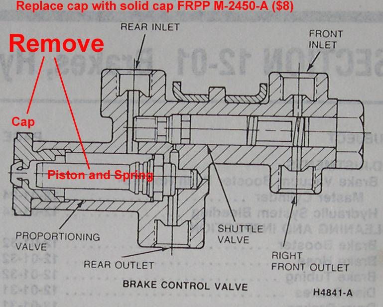
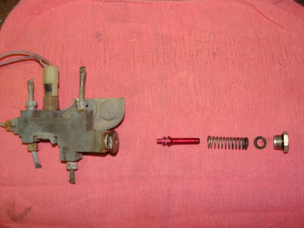
If you are going to install a manually-adjustable proportioning valve, it would plumb into the line coming out of the combination valve going to the rear brakes. If you do this though, you will need to remove the stock proportioning valve and spring from the combination valve as shown in the following example:
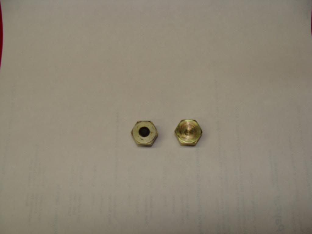
If the Granada (or similar Ford) combination valve has a black rubber plug in the center of the large cap on the end, you will have to replace the cap with one that is solid in design (no rubber plug in the center of it).
When the combination valve's proportiong components are in place inside the block, the seals on the stock proportioning valve spool isolates the plug (in the center of the large end cap) from any hydraulic pressure --no pressure/force is applied to the cap/rubberplug. Once you remove the stock, internal proportioning valve spool/seals all of the pressure would be applied to the large end cap. Obviously, if the cap was reused with the rubber plug in the center, the plug would be blown out the first time you stepped on the brakes --thus the reason for the need to swap to the solid end cap, if using this type valve with a manually-adjustable proportioning valve.
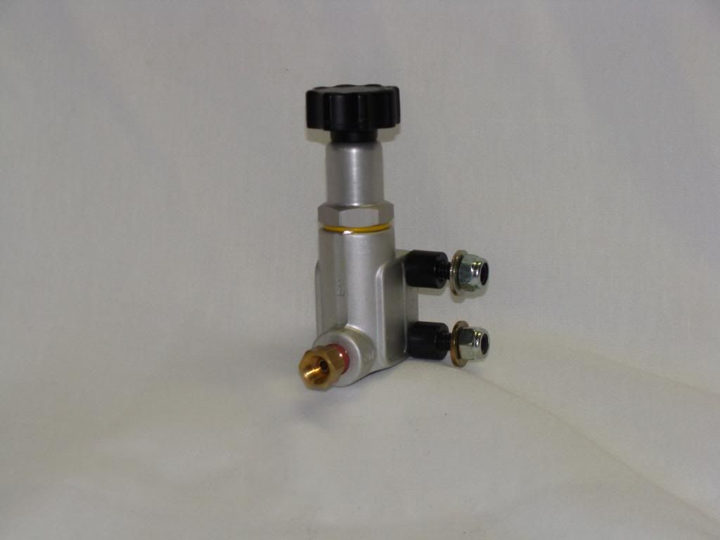
I've installed a number of manually-adjustable proportioning valves like this:
They look cool and all that but the reality is you don't really need one. The stock Granada (or similar Ford) disc/drum combination valve is more than capapble of handling the proper brake functions on its own. The manually-adjustable valves get set to one point and that's where they stay unless you twist on the knob again. If you really think about it, what are you (actually) setting it to? some balance between the rear wheels not locking up before the fronts? Ok, if you adjust it for some 'balance' between this, what is that setting and what does it really mean?
The factory did a good job in designing the stock combination disc/drum valve without needing a manually-adjustable proportioning valve. If you want to install the manually-adjustable valve then that's just a personal choice. If you do so and if you use the Ford Combination Valve, then you will need to make the modifications to the stock valve I mentioned above.
The dual master cylinder port closest to the firewall is the feed to the front brakes. The MC port closest to the radiator is the feed to the rear brakes.
Offline
Hey MS and Moderators, why not start a new heading in the index for "Sticky" or other saved high-info threads??
This is a good example of one.
Corky
Offline
ultrastang wrote:
'65/'66 Mustangs had single resevoir MCs. There would have been two lines coming out the front end of the original single pot MC (or least there are on the GT). One line would have lead directly to the rear brakes. The other would have gone over to a 3-port brass Tee mounted on the left, rear, inner fender apron. From there, one line on the Tee would have split off and gone to the left front caliper and the other line from the Tee would have gone to the right front caliper.
Now, you are going to a dual reservoir MC. The original Tee should serve no function in your current swap. You need to replace it with a disc/drum combination valve like is pictured below.
(Granada disc/drum Combination Valve)
This valve totally splits the brake system and has several internal functions important for the dissimilar brake components (discs on front, drums on rear) to operate correctly.
If you are going to install a manually-adjustable proportioning valve, it would plumb into the line coming out of the combination valve going to the rear brakes. If you do this though, you will need to remove the stock proportioning valve and spring from the combination valve as shown in the following example:
If the Granada (or similar Ford) combination valve has a black rubber plug in the center of the large cap on the end, you will have to replace the cap with one that is solid in design (no rubber plug in the center of it).
When the combination valve's proportiong components are in place inside the block, the seals on the stock proportioning valve spool isolates the plug (in the center of the large end cap) from any hydraulic pressure --no pressure/force is applied to the cap/rubberplug. Once you remove the stock, internal proportioning valve spool/seals all of the pressure would be applied to the large end cap. Obviously, if the cap was reused with the rubber plug in the center, the plug would be blown out the first time you stepped on the brakes --thus the reason for the need to swap to the solid end cap, if using this type valve with a manually-adjustable proportioning valve.
I've installed a number of manually-adjustable proportioning valves like this:
They look cool and all that but the reality is you don't really need one. The stock Granada (or similar Ford) disc/drum combination valve is more than capapble of handling the proper brake functions on its own. The manually-adjustable valves get set to one point and that's where they stay unless you twist on the knob again. If you really think about it, what are you (actually) setting it to? some balance between the rear wheels not locking up before the fronts? Ok, if you adjust it for some 'balance' between this, what is that setting and what does it really mean?
The factory did a good job in designing the stock combination disc/drum valve without needing a manually-adjustable proportioning valve. If you want to install the manually-adjustable valve then that's just a personal choice. If you do so and if you use the Ford Combination Valve, then you will need to make the modifications to the stock valve I mentioned above.
The dual master cylinder port closest to the firewall is the feed to the front brakes. The MC port closest to the radiator is the feed to the rear brakes.
I think the 65/66 OE stock Manual drum drum master cylinder single bowl only had ONE line coming out the front.
I think the OE stock POWER drum drum master cylinder single bowl had TWO ports coming out of MC.
I think the OE stock Manual Disc drum mastery cylinder single bowl had TWO ports and in addtion used the brass distribution block AND a a kelsey hayes prop valve as well.
I"M not sure what 6sally6 had on his car originally. but he didnt have disc brakes,
also MS pic and Ultrastang pic locates the MC inlet front and mc inlet rear ports differently in thier diagrams. which one is right? or does it not matter??
Offline
The valve pictured on my post is correct. It denotes which port on the master cylinder connects to that particular port. The others show whcih brake, front or rear, that feeds that port. Rather than leave room for confusion, I try to tell them which actual port on the master cylinder feeds that line. Alot of people do not realize the rear port on the mc feeds front brakes and front port feeds rear brakes. I think even my picture can stand to have some clarification, to make it totally clear.
These posts are a very good example of WHY someone posting a question should explain the details about what they are talking about. The various replies assumed he had a drum brake single pot master cylinder, a disc brake GT single pot master cylinder, a tandem master cylinder, an adjustable proportioning valve, a drum brake distribution block, a disc brake distribution block, etc etc. Everyone was trying to guess what the question really was because NO info was provided as to what was being installed. One would have to have been following 6sally6's previous posts very carefully to understand what he was working on. I had some inside information because I sold him the combination valve in the picture, and he had told me he had ordered a Maverick master cylinder, plus I had read the posts about the scarebird disc brake conversion. Not to pick on sal, but this is just a good example of how making the question as clear as possible will save everyone a lot of typing and most likely get better responses and a more accurate answer. OK, so much for the "MS SATURDAY SOAPBOX"
Offline
The labeling on the valve diagram says," Inlet (from M/C front)." If you interpret that to mean that you connect the Front Port of the MC to that port location on the valve, then you have just connected the part of the MC that's supposed to supply brake fluid to the REAR brakes.
The" Inlet (from M/C front)" means the line from the MC that supplies fluid to the front brakes should be connected to that location on the valve, not that the (physical) front port of the MC connects there. The (physical) rear port of the MC would be the port that connects to the "Inlet (from M/C front)."
Offline
ultrastang wrote:
The labeling on the valve diagram says," Inlet (from M/C front)." If you interpret that to mean that you connect the Front Port of the MC to that port location on the valve, then you have just connected the part of the MC that's supposed to supply brake fluid to the REAR brakes.
The" Inlet (from M/C front)" means the line from the MC that supplies fluid to the front brakes should be connected to that location on the valve, not that the (physical) front port of the MC connects there. The (physical) rear port of the MC would be the port that connects to the "Inlet (from M/C front)."
This is all 6sally6's fault, LOL. sorry to post that I was confused about MS and Ultrastang diagrams, but If i was confused I'm sure others were confused as well if they were actually paying attention to labeling of both of the diagrams. ANd when it comes to brakes, I'd rather get it clarified than to just let it go. Not trying to put out a fire with gasoline here...
EVEN though Ultrastang and MS were referring to the same thing in thier diagrams, both of your diagrams were confusing to a novice reader. MS diagram was referring to FRONT as a physical port on the MC. Ultrastangs diagram was referring to FRONT as the actual BRAKE SYSTEM BOWL on the mc which is physically the rear port. Clarification was needed. ANd you both were correct depending on how you read them. But I have no idea from those diagrams what you both had in mind when labeling FRONT on the inlet.
I made the assumption in my previous post that he originally had a drum drum single bowl mc setup which only has 1 line on it going to the T brass distribution block. Ultrastang made the assumption that he originally had a disc drum single bowl "GT" mc brake setup which has 2 lines on it going to the T Brass distribution block and the Kelsy hayes prop valve, and ultra gave instructions based on that. I'm really not sure if a disc/drum mc single bowl was specifically a GT thing or not. Maybe non GT cars had the disc/drum option. I don't know the answer to that. Point is that we both gave different plumbing instructions based on our assumptions.
sometimes it takes a person like me who is reading the replies as an novice and not as an expert, to question the expert replies that you both have given whenever its not clear or it appears to conflict with each other or from what I have read elsewhere.
I'm just trying to clear this all up for anyone else who reads this thread and reads my post and understands that my previous post is just for a drum drum setup and does not apply to those of you that originally have the GT or disc drum mc and are converting to front disc brakes with a dual bowl mc. My reply was specific to 6sally6 only and not to be taken as a RULE when doing your own disc brake or power disc brake conversion. As tubo states maybe a whole new thread or STICKY should be made on all the different OE stock configurations that existed before doing any kind of disc brake conversion, so that all the different type of plumbing configurations are explained ONCE and for all.
Offline
I rhink BOTH of our diagrams could have a better description as to where those lines come from. What it really needs is a picture of the MC right next to it to remova alll doubt.
Offline
MustangSteve wrote:
I Think BOTH of our diagrams could have a better description as to where those lines come from. What it really needs is a picture of the MC right next to it to remove all doubt.
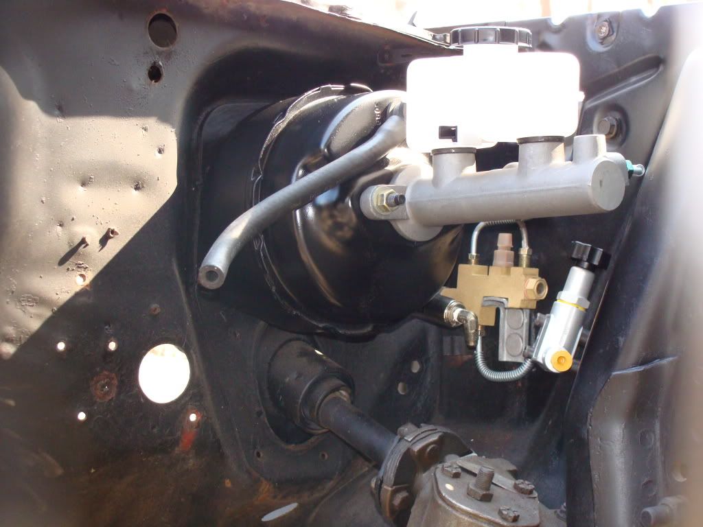
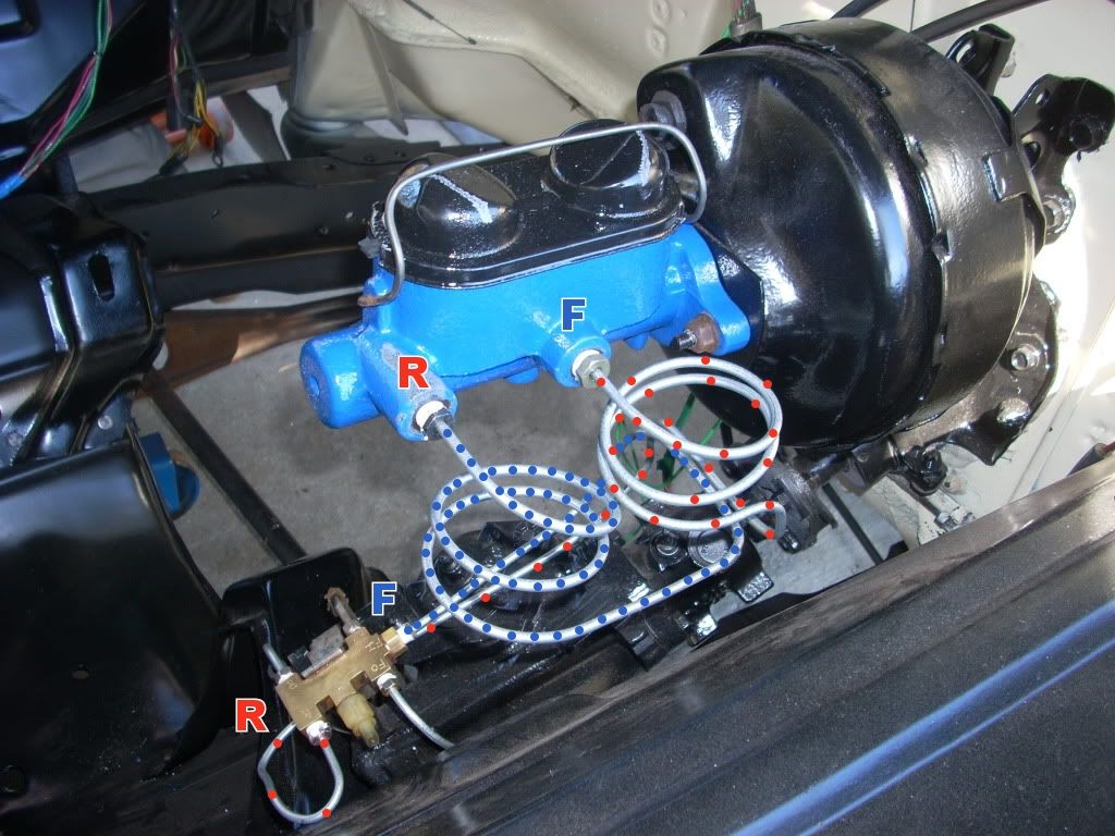
About 4 months ago, a guy from another forum posted this photo.
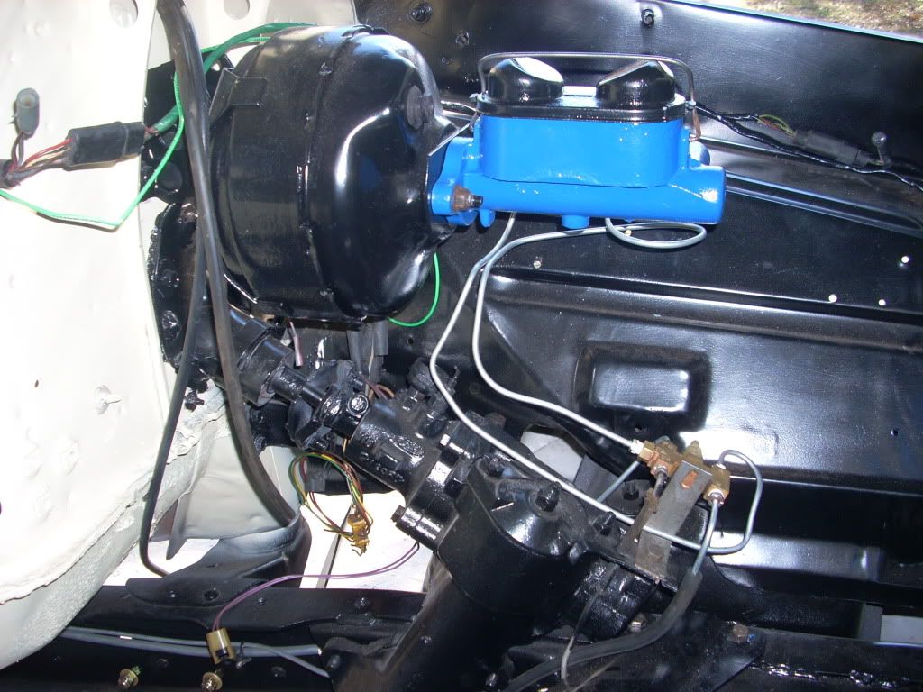
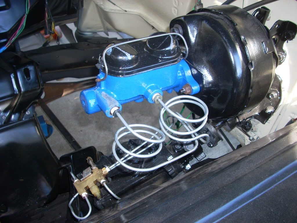
I immediately noticed something seemed wrong but couldn't be positve without seeing the other side of the MC to know where the lines were actually connected. I made a post that it looked like the lines were swapped on the MC. The guy got miffed at me for having the audacity to question his handy work. In an effort to "fix my wagon," he posted this picture to prove to me that I was wrong and that he didn't get it backwards.
After he posted this picture, it was no longer a matter of my suspicion that he plumbed it wrong. It was completely without a doubt, at that point, that he plumbed it wrong!
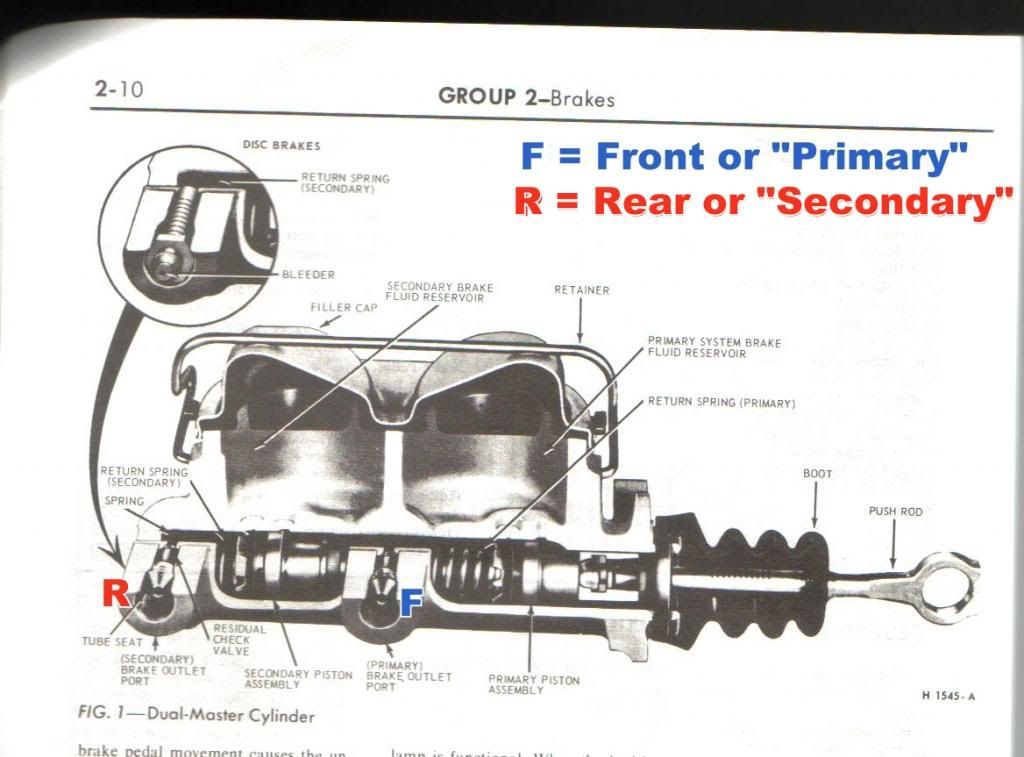
...Sooo, I took his own photo and labelled the ports with which port feeds which brake circuit and then posted this.
I took this picture from my shop manual and imposed an "F" and "R" (and what they equalled) so that he (and anyone/everyone else) would know that the (physical) front port of the MC does NOT go to the front circuit of the valve ("front" being the end of the valve that has (3) ports on it).
If you are doing brake work --such as changing MCs, doing a brake conversion or whatever, think of the above picture as if you are on Google Maps where "F" is the starting point of your destination. As long as you remember that the (physical) rear port of the MC is the feed to the front brakes and that the line from it goes to the end of the valve that has (3) ports, everything else will take care of itself.
Last edited by ultrastang (5/26/2013 12:12 PM)
Offline
MarkinSC wrote:
steve s. wrote:
i always run my lines from the master to the dist block, then plumb the prop valve into the line running from the dist block to the rear brakes.
I don't see how that is possible if you have a dual bowl mc. The stock single bowl master had 1 line to the brass block. A drum/drum dual bowl would have two lines coming out correct? A disc/drum would also have two lines coming out.
i did like the others, i "assumed" :-)...
my thinking was that "if" he was adding a stand alone prop valve for the rear, he was upgrading the brakes to a dual master & discs all the way around.
another thing that gets confusing is the use of the term "distribution block" & "proportioning valve/combination valve". in the hot rodding circles i grew up in, a distribution block is just that, a glorified "T", where the prop/combo valve has the "valve" part inside to regulate the rear brakes. take the valving out of a combination valve & its then a distribution block.
Offline
steve s. wrote:
MarkinSC wrote:
steve s. wrote:
i always run my lines from the master to the dist block, then plumb the prop valve into the line running from the dist block to the rear brakes.
I don't see how that is possible if you have a dual bowl mc. The stock single bowl master had 1 line to the brass block. A drum/drum dual bowl would have two lines coming out correct? A disc/drum would also have two lines coming out.
i did like the others, i "assumed" :-)...
my thinking was that "if" he was adding a stand alone prop valve for the rear, he was upgrading the brakes to a dual master & discs all the way around.
another thing that gets confusing is the use of the term "distribution block" & "proportioning valve/combination valve". in the hot rodding circles i grew up in, a distribution block is just that, a glorified "T", where the prop/combo valve has the "valve" part inside to regulate the rear brakes. take the valving out of a combination valve & its then a distribution block.
Prior to 1967, a Mustang brake system would have had a simple Tee (or manifold block) that the lines connected to. It would have had no internal mechanical functions. Beginning in 1967, government regulations required auto manufacturers to install split brake systems (dual reservoir MCs).
If the vehicle had drums all the way around (on a '67-later vehicle) then the MC would have connected to a pressure differential valve, or sometimes called a 'distribution valve.' This valve body has a spool inside that senses if there is a pressure drop (differential) between the front vs. rear brake circuits. If there is a drop in fluid pressure the spool shifts to the low pressure (failed) side to close that circuit off so that brake fluid isn't pumped out onto the ground, --which would empty the MC if there was no device to cut the fluid flow off.
If the vehicle had discs on the front and drums on the rear, then the MC (on a '67-later vehicle) would have connected to a combination valve --which is commonly called a 'proportioning valve' but proportioning is only ONE feature of what a combination valve does.
The disc/drum combination valve contains a pressure differential valve (just like the drum/drum valve), to warn of a pressure loss (brake failure). It also has a metering valve to momentarily hold off fluid to the front discs to give the rear drums time to overcome the tension of the retracting springs. The final feature of the combination valve is the proportioning of fluid to the rear drums.
So, in relation to 1967 and later Mustangs/Fords, a drum/drum pressure differential valve has only the one function of sensing a pressure drop and triggering the brake warning light on the dash. A disc/drum combination valve performs three functions; sensing for a pressure differential to warn of a brake circuit failure, the metering of fluid to the front discs and the proportioning of fluid to the rear drums.
Last edited by ultrastang (5/26/2013 8:12 PM)
Offline
OK,now that we have all THAT straightened out...
GOT IT, Sal?
Offline
MustangSteve wrote:
OK,now that we have all THAT straightened out...
GOT IT, Sal?
This can be VERY (mentally) tiring trying to explain all the brake configuration possiblities on Mustangs/Fords, and would be even harder to try and explain it with just text and no photos. It gets even more complicated trying to explain it when someone is going from a pre-'67 era brake system to needing brake components from a '67-up era and what parts need to be eliminated and what parts need to be added, to make the system work safely and correctly.
...I think I'm gonna let my brain rest now.
Last edited by ultrastang (5/26/2013 8:15 PM)
Offline
ultrastang wrote:
MustangSteve wrote:
OK,now that we have all THAT straightened out...
GOT IT, Sal?This can be VERY (mentally) tiring trying to explain all the brake configuration possiblities on Mustangs/Fords, and would be even harder to try and explain it with just text and no photos. It gets even more complicated trying to explain it when someone is going from a pre-'67 era brake system to needing brake components from a '67-up era and what parts need to be eliminated and what parts need to be added, to make the system work safely and correctly.
...I think I'm gonna let my brain rest now.
Why not start with all the possible OE stock brake configurations on the 64-66 models first. Include all the hardware (mc, single bowl small reserviour, single bowl large reserviour , single port or dual port, booster or no booster, drum drum no power, drum drum power, disc drum no power, brass distribution Tee block, kelsey hayes prop valve, rear brake hose single exhaust, rear brake hose dual exhaust. manual brake pedal, automatic brake pedal, brake switch, dash light, etc. ANd the options that were not available stock such as disc drum with power, or disc disc no power, disc disc power. Show the electrical diagrams for the stock OE configurations.
Lets at least start with all the OE stock configurations that were possible. Label them A-Z. hopefully this might help those that are missing components or have mismatched components to get them safely on the road with a correct stock configuration. Then list the upgrade paths they can take from point A, or point B, etc.
Mention the brake pedal bearings that wear and for people to check that.
Mention the pros and cons of each oe setup and as to why they evolved from A to Z.
Mention the forum mustang parts suppliers to support for stock OE parts, and parts suppliers for upgrade path parts.
Yeah its alot, but if its done once, then saved somewhere, then all that needs to be done is supply a link to that source instead of retyping information that may or may not be accurate, complete, or misunderstood by a reader each time a brake question comes up. Especially when it comes to many people giving out brake answers that can jeopardize someone who may have only read the first or second post which may be wrong, and never read subsequent replies that corrected previous posters.
i think this is important.
Offline
Good idea, Mark. Take pictures off all those configurations and I will label them and put them on the website.
Offline
Jeeperz I got a really big one! (Huh,Don!!)
Longest thread in quite a while.
And I thought disc brake stuff had been discussed to death!
Seems like everyone wants to share how they did it...buuteye failed to state all the stuff I have going. (Right MS!)
To make matters worse....I post the question and then hafta go out-of-town for a few days.
Looks like I have a gang of stuff to absorb but MS is right because he knows what ALL I have so far and what I'm trying to accomplish.
Even though I e-mailed Ultra a few times I didn't bring him up-to-date on the last piece of equipment I bought.
Looks like I don't need the stock distribution/splitter valve......the "proportioning" valve takes its place.
My next thang is rounding up all the different fittings to go from the MC>prop valve>brake lines>brake hoses>calipers.
Thanx folk,so far.
6sally6
PS.......... I pried the push rod out of the old manual MC to use in my new disc/drum MC. My question is..........do I just slide the old one in,or do I tap it in with a BFH, or will it kinda stay in place if I push it hard enough?! Don't wanna tear up my new stuff pushing in the old pushrod. Any hintz?
6s6
Last edited by 6sally6 (5/27/2013 8:28 PM)
Offline
Let the leverage of the brake pedal seat that rod once you get everything bled. That way the MC is held in place by the flanges and not in a vise where it might get distorted.
1 of 1
REMEMBER!!! When posting a question about your Mustang or other Ford on this forum, BE SURE to tell us what it is, what year, engine, etc so we have enough information to go on. |