| ||
Visit MustangSteve's web site to view some of my work and find details for: FYIFORD Contributors' PICTURES - Power Brake Retrofit Kits for 65-66 Stangs - Classic Mustang FAQ's by MustangSteve - How to wire in a Duraspark Ignition - Mustang Ride Height Pictures and Descriptions - Steel Bushings to fit Granada Spindles to Mustang Tie Rods - Visit my EBAY store MustangSteve Performance - How to Install Granada Disc Brakes MustangSteve's Disc Brake Swap Page - FYIFORD Acronyms for guide to all the acronyms used on this page - FYIFORD Important information and upcoming events |
1 of 1
Offline
Hi there.
Looks like I were right, it did not take a long time untillI posted something again. Yet again I have a question, hopfully someday I can help answer some aswell
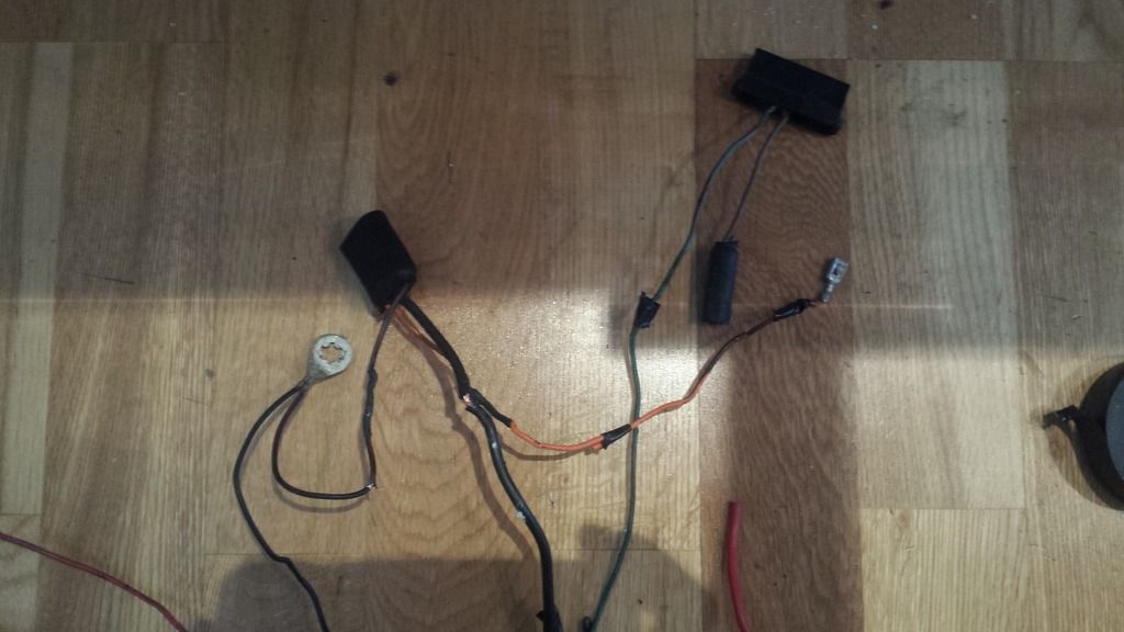
Since I use H4 headlights I figured it was a good idea to rebuild the harness so I could use relays on them, the harness is really old, so it wa a good opurtunity to overlook it at the same time, I disconnected everything and brought it inside, some repairs and splices had to be done
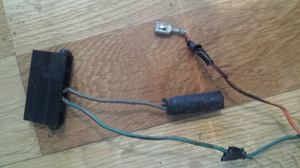
But when I got to the voltage regulator plug, it was a total mess, so here is my question;
the orange wire were loose and hanging outside the plug, where does this go?
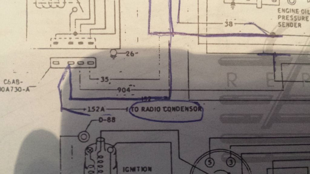
the green wires do not seem to mach the wiring diagram in my handbook, is it possible that the previous owner missplaced them?
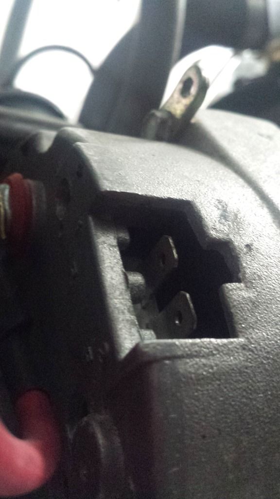
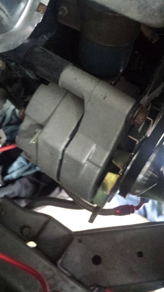
and, I think it looks like I have got an alternator with internal voltage regulator, do I even need the plug and external regulator? (the rubber plug where I belive that the alternator pigtail goes into were not hooked up to anything, and the entire pigtail is MIA.
Offline
Offline
hmmm ok, seems like it were not completly....... complete then I do not understand, I aqtually drove the car like this....
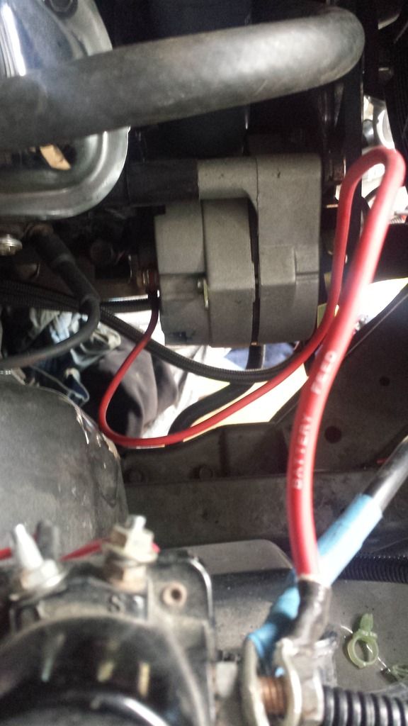
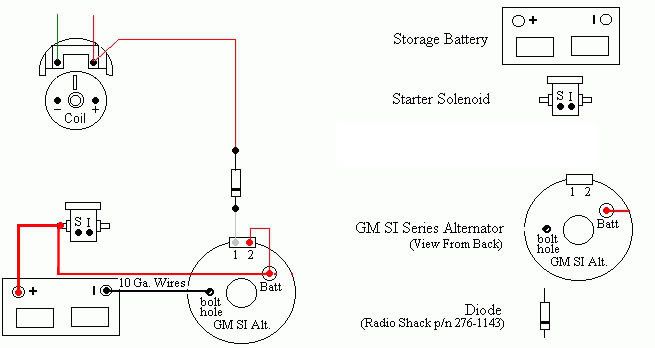
so...... I can scrap the regulator? and wire like this
I suppose the small lip on the laternator is for ground.... since it has worked-ish it must be grounded to the chassis....
I am not on safe ground here, that is for sure
Offline
[img]
\\&d=1319246099[/img]but it does not seem to match up with thisone.....Offline
to get everything working with charging lamp etc i assume I have to fix the original harness and use the regulator and wire like the last picture?
what I cannot figure out is that my harness does not mach up completly with the diagramhere is the radio-condensator plug wired with the green/black wire, but with my harness it looks like the condensator-plug is on the green/red wire, the green red wire in my diagram is the 904 and goes to coil,start and proveout, the 152 witch have the radio-coil plug in my diagram isgreen/black and goes to the starting motor relay.... that cable i cannot find in the harness atal, but that maby is not so strange, if it just was a small cable from the regulator to the starter relay, it may have come out of the plug at sometime and is missing compleatly?
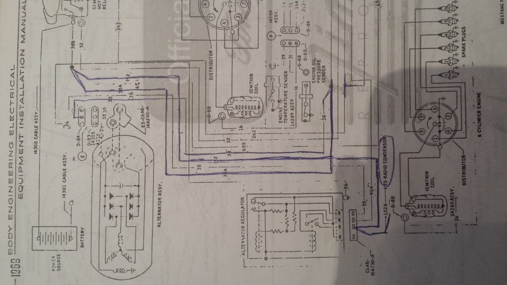
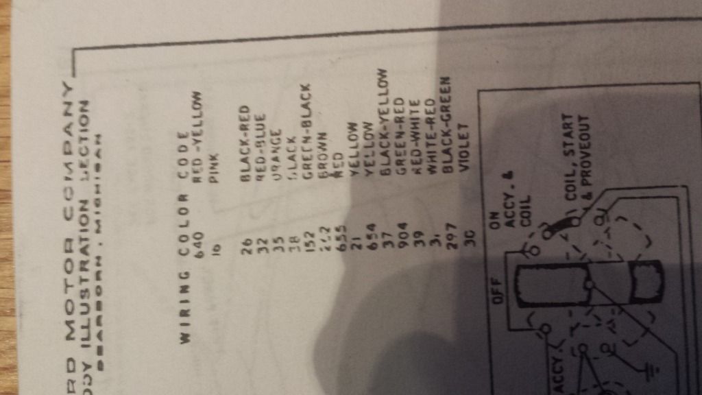
Last edited by esmi83 (5/31/2017 1:43 PM)
Offline
looks like a gm alternator to me
Offline
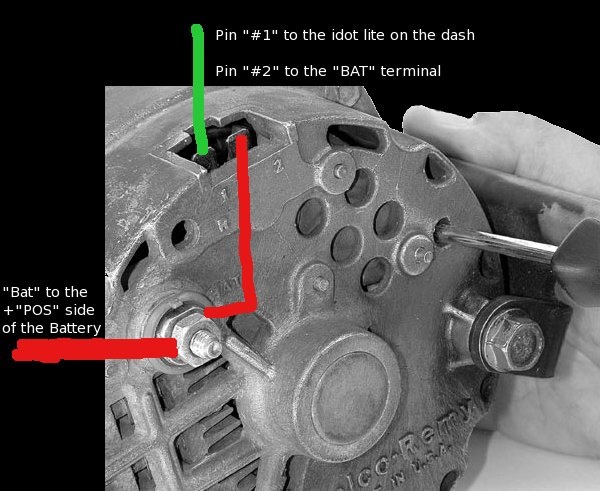
sooo I only need to jump the power to terminal number "2" and wire the "1" terminal to the orange wire that goes to the "field" terminal on the existing regulator? and then the green and red one sends signal to the charging lamp?
Last edited by esmi83 (6/07/2017 5:36 AM)
Offline
esmi83 wrote:
sooo I only need to jump the power to terminal number "2" and wire the "1" terminal to the orange wire that goes to the "field" terminal on the existing regulator? and then the green and red one sends signal to the charging lamp?
Terminal 2 is the voltage sensing terminal on the internal voltage regulator. If Terminal 2 is directly connected to the alternator BAT terminal as shown in your picture, that is the "One Wire Alternator" style hookup. It will work, but it is not optimal. Terminal 2 should be connected to the largest power distribtion block to read thevoltage drop caused by heavy current draw. If you have a very simple system, like an original 1st gen Mustang without A/C, then the factory connection at the starter solenoid will do. However, if you have modernized the car with a powerful stereo, an electric cooling fan, Air Conditioning, power windows, power locks, GPS, heated seats, etc, then Terminal 2 should be connected to the auxiliary power distribution block feeding all the accessories, to make sure the alternator is putting out enough voltage to compensate for the power draw voltage drop.
Anyone running a relocated, remote battery will have trouble charging their battery if they connect Terminal 2 to the alternator BAT terminal.
Offline
Aha, thanks mate, now I am slowly getting the grip of things
I do indeed have some electric acsessories... thanks!
The harness is like original, so the power to my acessories is actually picked from the +side on the starter relay, so that is what I would consider the main block, but would it be better to take the signal from another place? like the splice on the +cable before my headlight-relays?
Last edited by esmi83 (6/08/2017 2:47 AM)
Offline
esmi83 wrote:
Aha, thanks mate, now I am slowly getting the grip of things
I do indeed have some electric acsessories... thanks!
The harness is like original, so the power to my acessories is actually picked from the +side on the starter relay, so that is what I would consider the main block, but would it be better to take the signal from another place? like the splice on the +cable before my headlight-relays?
The wire supplying power to your headlight relays should be fused, so the Terminal2 connection should be made on the battery side of the fuse.
1 of 1
REMEMBER!!! When posting a question about your Mustang or other Ford on this forum, BE SURE to tell us what it is, what year, engine, etc so we have enough information to go on. |