|
FYI FORD - MustangSteve's Ford Mustang Forum The Internet's Most Knowledgeable Classic Mustang Information IF YOU HAVE A QUESTION ABOUT CLASSIC FORD MUSTANGS, YOU HAVE COME TO THE RIGHT PLACE! MustangSteve has over 30 years of Mustang experience, having owned 30 of them and restored several others. With the help of other Mustangers, this site is dedicated to helping anyone wanting to restore or modify their Mustang.... THERE ARE NO DUMB QUESTIONS!!!!! |
FYIFORD Contributors' PICTURES - Power Brake Retrofit Kits for 65-66 Stangs - Classic Mustang FAQ's by MustangSteve - How to wire in a Duraspark Ignition - Mustang Ride Height Pictures and Descriptions - Steel Bushings to fit Granada Spindles to Mustang Tie Rods - Visit my EBAY store MustangSteve Performance - How to Install Granada Disc Brakes MustangSteve's Disc Brake Swap Page - FYIFORD Acronyms for guide to all the acronyms used on this page - FYIFORD Important information and upcoming events


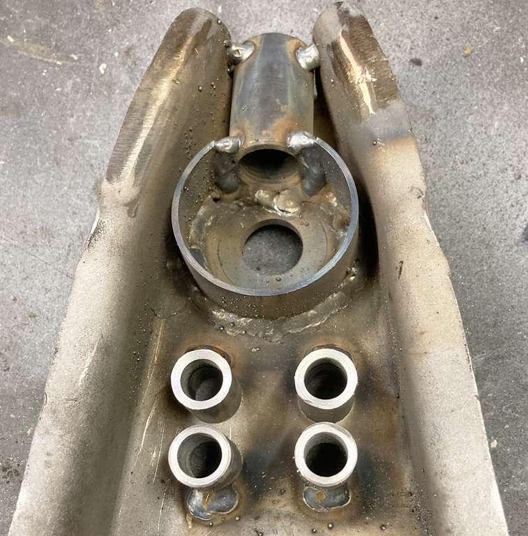
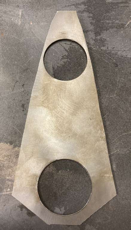
 Vkt-66 wrote:
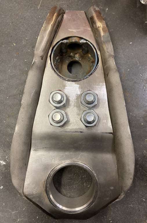
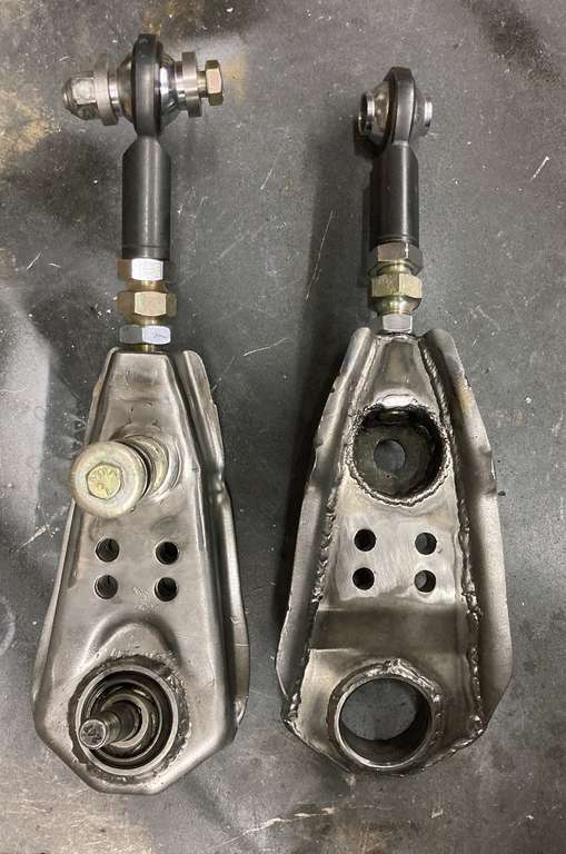